
Phase 3
With this assignment, students are tasked with refining their Medium Fidelity Prototype.
The imperatives for this assignment are that the final device must move, use an Internet of Things (IOT) control and must use Python Programming.
Assignment Blurb

Poster for Phase 3 Project


I am attempting to use the Ultrasonic Sensor on my robot car. I decided to use an Arduino Uno because I still want to keep the Blynk capability on my Raspberry Pi to control the existing headlights. I also may end up controlling the motors through Blynk, and therefore want to control it using the Raspberry Pi as well. I may transfer the ultrasonic to the Raspberry Pi later on, but for now I want to get it up-and-running with the Arduino.
The image above shows the wiring schematic. I will use the existing breadboard on the robot car.

Current wiring setup of the Ultrasonic sensor. It is pointing down now but will be pointing in the direction that the camera module is pointing in in the future.
Source code for the Ultrasonic Sensor Project. I am inputting this code on the Arduino IDE.


I ran into an error when uploading the code into the Arduino Uno. The error is an avrdude error, and states that the program can't open the device "//./COM4". I currently do not know what this error is, but I will troubleshoot it.

I changed the port for the Arduino on the Tools Tab of the Arduino IDE to COM3. I am suspecting this is what COM4 was referring to on the first error.
However, I still ran into errors, as shown above. It is another avrdude error.

Current setup of the Arduino Uno on the robot car. It is subject to changes later on, but for now is adequate.
I reinstalled the Arduino IDE to see if the errors would subside. Unfortunately, this did not solve the programming error.
I also ran a Blink program from the Arduino IDE code examples. It blinks the onboard LED light on and off to see if the program was able to be compiled and ran on the Arduino. No additional components were installed. The same error as shown above was prevalent.
The image below shows the Blink program:


New setup of the Ultrasonic sensor. I decided to directly connect the ultrasonic sensor to the Arduino Uno in order to simplify the setup.
I found a tutorial that covers the ultrasonic sensor for the Elegoo Uno R3. Eelgoo has an entire series of libraries for the Arduino Uno, including the HC-SR04 Ultrasonic Sensor. The zip file folder is called "HC-SR04" and is under the zip file download for the Super Starter kit.
I installed the library into my Arduino IDE.
I still ran into the same error when installing the library and running the source code. I verified the source code in the IDE, and it compiled successfully without error. I know the source of error is not with the code itself.
I will try to uninstall and completely reinstall the Arduino IDE. This may be unnecessary, but I want to be extra certain that the error will be eliminated.
I learned that the proper COM port needs to have "(Arduino Uno)" or "(Arduino Uno/Genuino Uno)" after its name. The COM3 port has neither.
The main issue is that COM3 is the only port option that I have. Even when I uninstalled or reinstalled the Arduino IDE, the issue remains the same.
I heard that I may have to manually install drivers for the Arduino Uno.
After checking the Device Manager, I could not find "Arduino Uno". It is supposed to be under "other devicess". but no such option exists.
The only other option is to attempt to install the drivers onto the Elegoo Uno R3, which is the same microcontroller but under a different brand.
I am not going to publish an image of the issue because I do not want to publicly release information about my device.
I attempted to install the drivers onto the Elegoo Uno R3 board as well. However, no Arduino devices were shown, either under the COM ports or the "unknown devices".
The only other thing I can think of to troubleshoot this is to use a different cable for the Arduino.
I replaced the cable with the cable that came with the Elegoo Uno R3 Kit. When I plugged in the cable to both the Arduino and Elegoo Unos, the device still was not recognized in the device manager.
I then changed USB ports on my laptop. I realized that I plugged the cable for the Unos into one that did not work. After plugging in the cable, the Ardunio and Elegoo Unos were recognized under "Ports (COM &LPT)". The Arduino Uno is related to port COM4, while the Elegoo Uno is related to port COM5.
I retested the cable that came with an Arduino Uno starter kit, and the cable works.
The drivers were automatically installed for the Unos when the Arduino IDE was installed.

The code now successfully uploads to the Arduino Uno. However, when I check the Serial Monitor for Ultrasonic Sensor Distances, no distance values are published. I do not know why this is.

I found that the issue was that I forgot to input the code under the provided void loop. This command defines a variable equal to the command that retrieves the distance read by the sensor, then prints that value into the Serial Monitor. Since it is a void loop, it repeats infinetly. This happens every 1000 milliseconds, or one second.
Two videos of the Ultrasonic sensor inputting values. The left video shows the values being displayed on the Serial Monitor. The right video shows a graphical representation of the values on the Serial Plotter.
The values can be relatively inconsistent, and there are some extremely high values. I am not sure what causes this, and the tutorial that I viewed also does not have an explanation. However, this is not a major issue at the moment.
Source code for the Ultrasonic Sensor. This is from the second tutorial.


I am adding the Prototype Expansion Module from the Elegoo Uno R3 Kit. I am doing this in case I want to add multiple components to the system without adding a separate breadboard. The image to the left shows the module standalone, while the right image shows the module mounted on the Arduino Uno.

7/22/2021

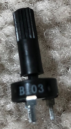
I am adding the LCD screen from the Elegoo Uno R3 Kit to the Ultrasonic sensor to publish the distance values. The left shows the screen, while the right shows a 10 kiloohm potentiometer.

I am using the prototype expansion model in order to wire multiple components to one port on the Arduino Uno. I used the small breadboard to connect both the Ultrasonic sensor and the LCD display to the 5V power source and Ground on the Arduino Uno. I also had to connect ports from each device onto digital ports 11 and 12 on the Arduino Uno.
.jpg)
When I powered on the LCD screen, there was a lit-up screen. I also ran a "Hello World" program from the Elegoo Super Starter Kit that provided a program to illustrate "Hello World" on the LCD Screen. However, when I ran it, no program entered on screen. I suspect this is a wiring error.
The text file below shows the "Hello World" program.
Source: https://www.elegoo.com/pages/arduino-kits-support-files
I tested the Ultrasonic Sensor program with the new wiring setup. The Ultrasonic Sensor still works as usual.
I moved on to using the Blynk application because I wanted to get something up and running for the Ultrasonic sensor. I saw a few tutorials on installing Blynk on the Arduino Uno.
Source Code for the Blynk application. The source code is useful for running a program to connect the Blynk application to the Arduino Uno, but not for controlling components over it.
Source: https://examples.blynk.cc/?board=Arduino%20Uno&shield=Serial%20or%20USB&example=Widgets%2FTerminal
The issue that I ran into was that I had to find the appropriate script and install a program called "Socat". I had difficulty with this part of the setup. The setup also does not include the Ultrasonic Sensor. I will try something else.


I replaced the cable that connects the portable phone charger to the Raspberry Pi. I moved the Raspberry Pi backward to just in front of the L298N motor driver, in order to seat the Arduino Uno up front.
this is to reduce the amount of loose wires and cables protruding out, which reduces the chances of the wires being caught and snagged on something.
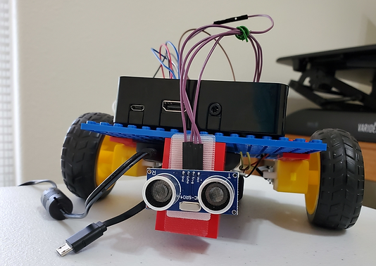
Below is an image of the current setup of the car.

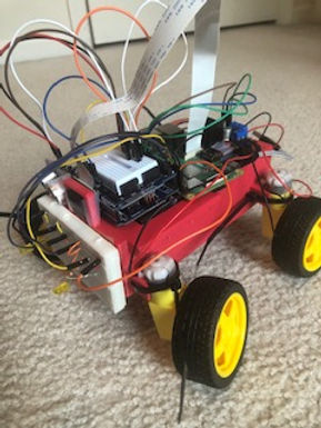
Setup of the robot car without the LCD display. I removed it because I am thinking about adding different components. The LCD also took up a lot of room for the given space on the robot car. I may add it later, but I am unsure about what I want to do with illustrating Ultrasonic Sensor values.
7/23/2021
The Ultrasonic Sensor has been reading values of 0 when the program was running. Today, I directly wired the Ultrasonic Sensor to the Arduino ports to see if I could regain the variable sensor readings again. Luckily, when I ran the program, the sensor was reading like normal. I will still rewire back into the prototype expansion module, since I may add other components to the Arduino.


Rewiring the Ultrasonic Sensor on the Prototype Expansion Module. The Ultrasonic Sensor still reads values properly.

I learned that the portable phone charger can be used to power the Arduino Uno. I do not know if this will affect any software program ran through the Arduino, since cable is the same cable and uses the same connection port as the software input.
7/24/2021
I am attempting to convert the input for the Ultrasonic Sensor from the Arduino Uno to the Raspberry PI. Not only will this consolidate everything to one system, it will also allow me to more easily connect it to Blynk.
I am using Joseph Petite's project as a guide to set this up. Special thank you to him.

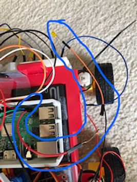
Current wiring setup of the Ultrasonic Sensor.
The problem that I am running into is that even though the code runs well, and the Raspberry Pi is connected to the Blynk application, no values are being displayed on the screen.
I found that the error was rather simple. Instead of connecting the Echo pin on the Ultrasonic Sensor into GPIO pin 24, which was determined by the program, I plugged it into GPIO pin 25. I solved the error by plugging the Echo pin wire into GPIO pin 24.

The left video shows a screen recording of the Ultrasonic Sensor values being read through Blynk. The right image shows an image of the current overall layout of the controls over Blynk.
Source code of the code for the Ultrasonic Sensor. It is directly copied from Joey Petite's Github document of the code.
Source: https://github.com/JoeyPetite/Phase-2/blob/main/US.py
I am attempting to connect a servo motor to the Raspberry Pi and using Blynk as well. I am also using Joseph Petite's project as a guide for this as well.
I wired the Servo Motor according to how Joseph connected the Servo motor to the Raspberry Pi. I am also using his code as a source code for the project. I also set up the slider module in a very similar way to how he did so.
Initially, when I entered the code and wired the motor, the Servo motor would not run when I set up everything. The only error that I ran into was that the source code had a runtime error, stating that the channel in line 11 had already been in use.
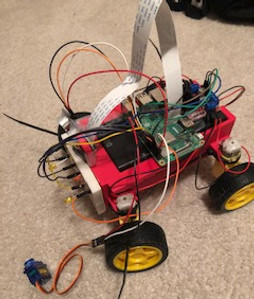
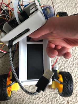
Image of the current setup on the robot at the end of 7/24/2021
7/25/2021
I found that the issue with the servo motor slider is that the range of output values was way too large for the servo motor program to read. I left the output values at the original 0 to 255, but the values needed to be from 4 to 12.5.

Video of the servo motor being controlled by Blynk.
I am now attempting to control the robot through Blynk. To do this, I am using Joseph Petite's project as a guide. Special thank you to him for the reference.
I am using his source code as a reference, but I modified the authentication code, the GPIO pins for the motors and the names of the motor variables in the code.
Source Code: https://github.com/JoeyPetite/Phase-2/blob/main/Phase2.py
At first, when I ran the program through Thonny IDE and ran the Blynk application, when I pressed all four buttons to indicate directions, the robot did not move.
The modified source code ran without errors, and the Blynk program indicated that the Raspberry Pi was connected and communicating with the Blynk application.
The source code powers both the motors to the robot and the Ultrasonic Sensor. The Ultrasonic Sensor portion of the code is working, with the sensor still reading numbers in the Blynk application.
7/26/2021
This morning, I collaborated with Professor Fagan to troubleshoot the Blynk controls for the robot. We troubleshooted the code syntax, as well as
--
We discovered that the issue was rather simple: I did not power the motor driver when I ran the code.


Just recieved the 3D prints of the housing units and the protective case for the Raspberry Pi. In my opinion, the prints did not turn out as I liked them. On the housing unit, most of the posts for the motor driver and Raspberry Pi to seat on broke off. On the case, one of the catch mechanisms broke off , and the guide does not align on the case to seat properly.

I tested the clearance for the phone case over the bridge type mechanism that the case for the Raspberry Pi and motor driver seats on. Unfortunately, the portable phone charger does not fit inside its compartment. This iteration of the housing unit will NOT be used.

Adding the Servo motor as a mount for the camera. I placed the Ultrasonic Sensor on the other side of the camera mount on the housing unit. The camera module will rotate vertically relative to how the robot car is positioned on the ground.
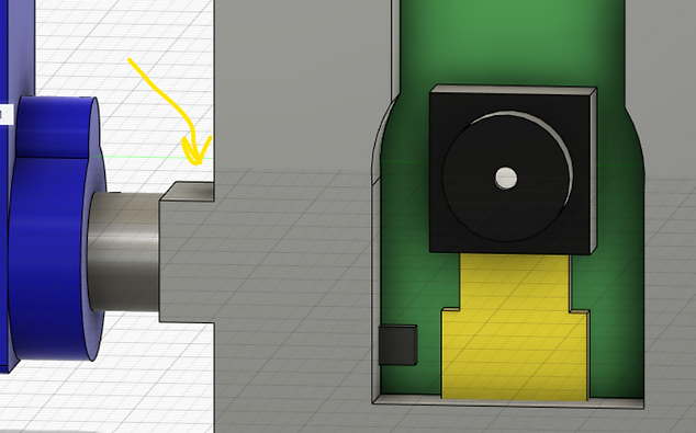
I plan on mounting the camera so that the lens is facing directly upward in the position shown in the image to the left. This will be an extreme point for the movement of the camera, and the lens will move downward.
Note that the mount is nowhere close to ideal; this is mounted on the first iteration of the housing unit. On the first iteration, there was a mount for the camera module that only allowed for a stationary camera.

I am attempting to create a bracket for the Camera Module to mount onto the SG90 Servo motor. I plan on using the file to the left as reference, and I plan on using projection to make a connecting profile that matches the top gear for mounting the brackets.
I converted the SLDPRT File into a STEP file and imported it into Fusion 360.
Soruce: https://grabcad.com/library/tower-pro-micro-servo-9g-sg90-1

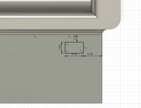
I am creating the mounting piece that goes onto the Servo Motor. I created a projection with an offset of +0.3 mm. I then created a two-way extrusion.

I downloaded a SLDPRT File for the Camera Module for the Raspberry Pi, to use as a reference file for the design. I converted this file into a STEP File and imported it into Fusion 360.
Source: https://grabcad.com/library/raspberry-pi-camera-rev-1-3-1


Positioning the Components in place to create the bracket. I want to align the components properly so that it is easier to more realistically model the bracket to the proper proportions.
The upper image shows the original positioning, while the lower image shows the components oriented with the Camera Module pointed "upside down". This is the proper way for the Camera Module to be set up because the cable for the Camera Module points upward to connect to the Raspberry Pi.


I am adding a backing to the Camera Module. Originally, I created projections and a -0.35 mm offset on the holes to create posts. However, the bracket is positioned at the back of the Camera Module, and I did not want to add posts since I had to extrude backward relative to the position of the Camera Module.


I redid the sketch and extrusion for the backing body. The reason is that I want the bracket to seat in front of the camera Module relative to where the Camera Module is filming. I also created an opening for both the camera itself and the protrusions below it.


I am adding a holder to support the Camera Module. Initially, I wanted to create posts that seat inside the holes provided by the module. However, when I recieved the 3D prints today, the posts snapped off cleanly. I do not want to risk this again. Therefore, I am creating a more structurally sound support.
I started by creating an offset plane with the bottom surface of the Camera Module as the reference. I then created a sketch encompassing the entire depth of the Camera module (relative to the direction that the Camera Module is filming), then creating 0.35 mm offsets for both portions of the bottom of the module.

Creating the Extrusion for the Camera Module holder. I extruded up until a few millimeters below the mount for the DSI cable in order to provide enough room for the holder slide mechanism to move up and down.

I modified the sketch for the extrusion on the Camera Module Backing. I added an opening above the camera in order to allow the Camera Module to slide freely up and down the holder without the camera interfering with anything. Since the camera is seated in a holder instead of seating on posts, this was necessary in order for the Camera Module to slide in and out.

I removed the offset for the black component in the sketch for the holder. Even though it is present in this reference file, it is not present on my Camera Module. removing the opening for it would make the housing more secure for my module.
Reinforcing the connecting piece that attaches the holder to the Servo Motor. This will help prevent the holder from breaking in half where the holder meets its mounting point.


Adding Fillets to most of the edges of the holder. This is to prevent any sharp edges from cutting, and potentially damage the Camera Module, as well as help prevent users from being cut by the sharp edges. The fillets may also help reduce stress concentration in certain areas.


Inside the mount for the holder on the Servo Motor, there was a gap between the projection used to create the mount and the cylindrical extrusion used to reinforce it. In order to remove the gap, I created a projection as the previous projection but on the reinforcing cylinder. I also created an extrusion on the inside body of the projection in order to prevent the opening for the Servo Motor to stick into from being filled in.
First iteration of the Camera Module holder to be 3D printed.
3D Printer G Code Settings:
-
Base Layer: Raft
-
Layer Height: 0.103 mm
-
Infill Density: 0.2 (20%)
-
Number of Shells: 2
-
Support Type: Dissolvable Column


7/27/2021


I am attempting to create a new iteration of the housing unit. I decided to import both iterations into one design, then create an iteration that uses features from both. For example, I like the motor housings on the second iteration, but I like how the components from the first iteration fit.
I isolated the design to the first iteration of the housing unit. I removed the original camera module, since I am using a servo motor to rotate the Camera Module.


I expanded the opening for both the Portable Phone Charger and Battery Pack, similar to the dimensions of the second iteration.

I am adding a reference file of the Servo Motor into the design, in order to create a mount for it. The Servo motor will mount onto the housing unit, and will completely hold the Camera Module. The Camera Module will not be directly mounted onto the housing unit.
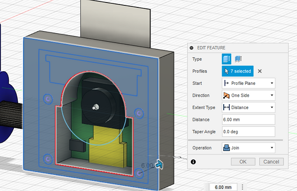
I am creating an extrusion for the Servo Motor mount. I am creating a projection with a 0.5 mm offset.


I inserted the Camera Module holder created yesterday into the housing unit as a reference file. I also moved it onto the Servo Motor as if it were attached, and created a rigid group with both bodies.


Creating extrusions under the Servo Motor holder, since the holder protrudes over the edge of the housing unit.


Creating an opening for the Servo Motor mount pinion to protrude through. I used a projection to create a center point for creating a circular sketch.
Creating the extrusions for the Servo Motor mount pinion in order to allow it to protrude and connect to the Camera Module Mount. I also added an opening above the hole in order to allow the pinion to slide into position.


Widening the opening for the Portable Phone Charger. I want to increase the opening to make the USB ports more accessible to connect the Raspberry Pi.
I rotated the motor housing and made modifications to the housing. I want to mount the motors horizontally relative to the ground instead of vertically. This will lower the center of gravity and make the robot more stabe. It will also lower the ride height of the robot, and potentially make it slightly more agile.


The modified motor mounts. Not only did I rotate them horizontally (relative to the ground), I also squared off the mounts and increased their length of contact with the motors themselves. This makes the motors more secure in their mount.

Creating an opening at the front of the housing unit for the L298N motor driver. This will make the motor driver more secure and the overall profile of the robot car.


Adding rounds to the opening for the L298N motor driver.

I imported reference files for both the L298N motor driver and HC-SR04 Ultrasonic Sensor. I am attempting to create and refine housings for both components.
HC-SR04 Ultrasonic Sensor Source: https://grabcad.com/library/hc-sr04-ultrasonic-sensor-8
L298N Motor Driver Source: https://drive.google.com/drive/folders/1j3aRdZzISUSH5uV6mCoRdNG1AbujW3u1


I created a holder for the Ultrasonic Sensor. I used projections to create the sketch for the cylindrical transmitter and reciever. I also added a projection to create a profile for the oval component.
I used 0.6 mm offsets in order to provide enough clearance for these components to properly seat into the holder.
Recreating the openings for the Zip Tie fasteners. I am still using Zip Ties because they are able to adequately secure them, and I want to see how effective they are with this new, more secure motor housing unit.
I moved the wiring opening for the motor driver mount closer toward the servo motor mount. This is in order to create more surface area for the Ultrasonic Sensor mount to seat on.

I started the print for the third iteration of the housing unit.
G Code Specifications:
-
Base Layer: Raft
-
Layer Height: 0.203
-
Infill: 0.25 (25%)
-
Number of Shells: 2
-
Support Type: Dissolvable- Tapered
-
Print Material: Black ASA
-
Support Material: SR-30

I converted the slider for the Servo Motor from a Horizontal Slider to a Vertical Slider. I did this because the Camera Module is going to rotate and move up and down vertically relative to the ground (instead of horizontally).

7/29/2021
I am planning on adding an obstacle avoidance component to the robot car. I found a resource called "Automatic Addison", who provided a tutorial on how to build a robot with obstacle avoidance. The resource even includes source code for it.
The image below is the example car from the project. The components used for this car are already presnet on my robot car.
Source: https://automaticaddison.com/how-to-make-an-obstacle-avoiding-robot-using-raspberry-pi/
Source Code for the Obstacle Avoiding Robot Project. The code is called "Obstacle_Avoiding_Robot.py"
I changed the Trig value from 23 to 18. I also changed the left motor GPIO pins from 22 and 27 to 16 and 19, as well as the right motor GPIO pins from 17 and 18 to 20 and 26, respectively.
Source: https://automaticaddison.com/how-to-make-an-obstacle-avoiding-robot-using-raspberry-pi/

Test run of the obstacle avoidance code. The robot ran into the wall and did not turn around properly. What I believe happened is that the robot car accelerated very quickly, and the Ultrasonic Sensor did not have enough time to trigger the code in order for it to command the motors to turn around.
The 3D print stopped running due to warping issues. Therefore, before I reprinted the assembly, I made a modification. I realized that the wires from the battery pack would not be long enough to directly connect to the motor driver. Therefore, I created an opening to allow the wires to protrude through in order to connect to the motor driver.

I modified the source code for the Obstacle Avoiding Robot project. I realized that the problem with the first iteration run was that the robot was moving right initially, then moving forward, instead of the opposite. I therefore changed the order of the GPIO pins for the right motors, from 20 and 26 to 26 and 20. I also experimented with swapping the robot.right direction command in place of the robot.forward command and vice-versa (under the if-else statement), but ended up going back to the original orientation.
I also increased the distance that the Ultrsonic Sensor reads before the robot car turns around to 25 cm from 15 cm originally. This is because the momentum of the motors still causes the wheels to move forward even after the Ultrsonic Sensor reading commands the robot to change directions. The momentum of the robot would still cause the robot to crash into an object even though the commands were activated.
Running the robot with the second iteration of the Obstacle Avoidance code. The robot does not crash like with the first iteration, but it does seem to turn away from obstacles very quickly and almost randomly. I think I overcompensated the distance from the obstacle that the robot needs to turn, and therfore the robot turns too quickly.
I am attempting to create a new iteration of the protective case for the Raspberry Pi. The first case, while being a great skill-building activity, had a broken catch mechanism shortly after I collected the print. In order to prevent this, I plan on making a case with an open top, but with only one piece.

I removed the guides for both halves of the case, since I will be printing this case as one body.

I removed the openings for the top, since I will be completely opening the top of the case.

Opening the top portion of the case, as shown by the left image, and adding fillets to the top perimeter, as shown by the right image.


Increasing the width and length dimensions of the case by 2.5 mm. This is because the Raspberry Pi had a hard time seating into the first case, and the fit was extremely tight. I believe this will give enough clearance for the Raspberry Pi to easily slide in and out.

Extending the opening for the SD card upward in order to allow the SD card to easily slide in and out of the case.


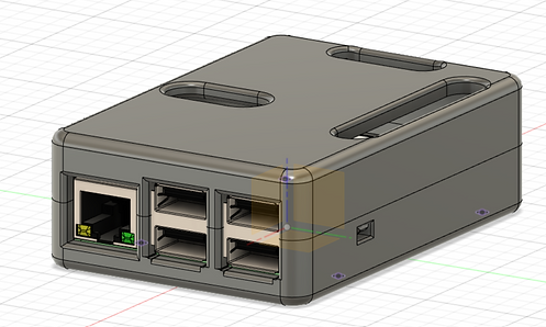
Creating an opening for the Cable Ports (Ethernet and USB ports) in order for the Ports to slide in and out of the case.

Starting the print for the second iteration of the protective case for the Raspberry Pi.
G Code Specifications:
-
Base Layer: Raft
-
Layer Height: 0.153 mm
-
Infill Density: 0.25 (25%)
-
Number of Shells: 2
-
Support Type: Breakaway- Model Material
-
Structural Material: "Tough"
-
Support Material: PVA Nat
I have been running into errors with the Blynk Servo Motor project. Even though the Blynk code runs relativley well (besides a runtime error with the "GPIO.setup(servo, GPIO.OUT)" command), and the Blynk application states that it recognizes the Raspberry Pi and Blynk Code, the motor will still not move with the Blynk application controls. The only two things I can think of to solve this issue are that there is an issue with the runtime error and there is an issue with the Servo Motor itself.
The odd component to this issue was that this project with the same Python code and the same specifications on the slider unit that controls the Servo was ran earlier, and it worked perfectly fine. The only difference was that I exchanged the horizontal slider for a vertical slider and rearranged some of the modules in the layout of the application. The slider still has the same specifications as the original slider.
I tested the 5V GPIO pins by connecting the Ultrasonic Sensor to both pins, and running its program. Both 5V pins work properly, so the source of error is not the power source (5V input).
The following text file is a source code given to us by Professor Fagan. Special thank you to him for access to several source codes. I modified the code by setting the servo1 GPIO pin to pin 12, since this is how my Servo motor is wired currently. When I ran the code however, the motor did not move.
7/29/2021
I found out that the "GPIO.BOARD" setup command converts the pin output to board layout (see Lessons Learned). Therefore, you associate GPIO pins by their relative location and order, instead of the specific GPIO pin designation.
I changed the pin according to the board layout, changing the servo1 variable from 12 to 32. However, even when I did this, the Servo still did not move. I am suspecting that the Servo Motor does not work properly, since the motor did not move with a code that is known to work.

I collected the protective case for the Raspberry Pi. While the Raspberry Pi fits inside the opening, with some clearance, there are a few minute details that could be impoved upon. The posts around the USB and Ethernet ports are not the strongest structurally, and one post broke off. The height dimension of the opening for the MicroUSB, HDMI and audio ports are also slightly too small, since the cables either interfere with the bottom or top wall of the setup.
I do not know if I did not optimize the print settings, or if I am simply overestimating the strength of 3D printed Polymer, but I am not impressed with the strength of the "Tough" material, since a post with a relatively wide base broke off. I do not know if it is because of how the print lines are structured on the print, or if the polymer is not made to be strong enough to support small posts.
I am setting another print for the Camera Module Mount. I have changed materials to the ABS material in order to see if it has good properties, as well as can reliably print, since the "Tough" material had issues with the prints.
G Code Specifications:
-
Base Layer: Raft
-
Layer Height: 0.153 mm
-
Infill: 0.2 (20%)
-
Support Type: Breakaway- Support Material
-
Structural Material: Black ABS

With the Servo Motor program, I changed the GPIO pin that the Servo Motor plugs into, in case there was an error with the GPIO pin. I moved from GPIO pin 12 (pin 32) to GPIO pin 6 (pin 31). However, when I ran the program, the Servo Motor still did not work.
At first, I ran a separate source code, as shown in the text file below, from the Introduction to Python Assignment through the Servo Motor, in case the codes I ran were faulty. I know this source code works, since it was used to power the Servo in the Introduction to Python Assignment. However, when I ran the code, the Servo Motor still does not work.
I then decided to replace the Servo Motor. I had a spare Servo Motor that I used in place of the original. This solved the problem for running the source code below.
Video of the Blynk Servo Motor project.
7/30/2021
I am attempting to add multiple Blynk projects into one program, in order to be able to control multiple functyions with one code and run them simultaneously on Blynk. For example, and the example I did, was combine my Blynk Servo Motor project with the Blynk robot project.
I used Joseph Petite's source code as a guide for this project. Special thank you to him for this. I used the functions to create the source code according to the text file below. I used Joseph's source code and input my previous codes for the def one() and def two() functions.
Source: https://github.com/JoeyPetite/Phase-2/blob/main/MasterCode.py
Video of the file that combines both codes into one. The left video shows the motors moving while the robot was suspended in the air, while the right video shows the code while the robot car was moving on the ground.
I am attempting to add the Blynk headlights project into the import code. However, when I ran the code, the headlights did not work. The text file is the code that I have.
7/31/2021
I am continuing to troubleshoot the inclusion of the Blynk headlight project into the multiprocessing program. I removed the Servo motor code from the multiprocessing in case the multiprocessing program can only take two programs at one time. However, when I ran the program, the headlights code did not operate, and the Servo Motor still moved when I tested it by manipulating the slider.
I do not know why the Servo motor also kept being operational even when its code was not called in the process. I can only speculate that the Servo Motor project code was also activated beforehand, and it has to be manually stopped. Essentially, it can run alongside the multiprocessing code.
I ran the Blynk headlights code exclusively, and experienced a similar situation. The headlights were able to turn on and off, but I was also able to control the Servo Motor and drive the robot itself. I did not make any modifications to the code beside exchange the correct authentication token for the one that matches my application. I did not add any commands to control either the Servo Motor or the DC motors on the robot. I also stopped the other programs before running this program.
There must be some part of another program controlling these features even when the code has stopped running. I do not know what this would be. I know it is not a pure electrical connection to the motors because the motors are not continually turning, and are still able to be manipulated through the Blynk program, exactly the same as running their respective codes.
8/1/2021


I found out about the "tabs" widgets in the Blynk application. I found out that the tabs allow users to add widgets in another page, instead of extending the first page. Fortunately for this application, the tabs widget does not cost any "energy balance", which means it does not expend any capability for me to add widgets.
I added the tabs in order to prevent the need to scroll through the application. Scrolling hindered my ability to slide the Servo slider up and down, since when I moved the slider up and down, the screen would also move up and down, but the slider would not move. With two tabs, I can keep all of the widgets while still keeping everything in one screen without scrolling.


I changed the input pins for the right headlight button from V1 to V6 and the button to control both headlights from V2 to V7. I did this because I also controlled the forward and backward function of controlling the robot with V1 and V2 as well. When I pressed the right headlight button, the forward button would also be pressed, and the robot would move forward. When I pressed the both headlights button, the robot would move backward. Changing the input pins fixes this problem.
The text file below is a copy of the current iteration of the code.
I am attempting to add a joystick component to the Blynk program. I am using Yinfei Li's project as a guide for the project. Special thank you to him for this.
Source: https://github.com/leeinfy/MEGR3090_Robot/blob/main/Phase2Blynk.py
I also added PWM connections for the L298N motor driver. I connected the PWM input for the left motors to GPIO pin 11, since this was the associated GPIO pin in the original program. I also connected the PWM for the right motors to GPIO pin 22 since this was also the associated GPIO pin in the original program.
The error I first ran into was the "rightmotorPWM" command. The command used the left_motor_speed_pin command as one of its refernces. The issue is that this variable is already being used for determining the PWM value of the left motor (leftmotorPWM).
I changed the rightmotorPWM command to be associated with the right_motor_speed_pin instead of the left_motor_speed_pin command. This removed the error, but it may cause other issues in the program later on.
I found out that I forgot to turn on the motor driver again, which was the reason why the motors would still not move, even when the program was entered. After this, the motors were able to move when the robot was turned on.
I tried reversing the "rightmotorPWM" back to using the left_motor_speed_pin association. However, I ran into the same traceback error, and the Blynk app showed that the Raspberry Pi was still disconnected. I then went back to using the modified version.
The directions of the motors have to be changed. When the joystick indicates forward movement, the robot moves to the left. When the joystick indicates backward movement, the robot moves to the right. When the joystick indicates left movement, the robot moves to the right and when the joystick indicates right movement, the robot moves to the left.
I changed the orientation of the GPIO pins in order to fix the direction problem. I changed the left motors from 16 and 19 to 19 and 16 respectively. I changed the right motors from 20 and 26 to 26 and 20 respectively. The result is that the robot moved in the opposite direction of the above orientation for each joystick. This solved the left and right joystick associations, but did not fix the forward and backward associations. It only switched the turning direction.
I also commented out the blynk.handle_event for pin V2, since it was used to control a slider for motor speed. This is currently unnecessary for controlling the joystick, but may be necessary for controlling the speed of the motors.
I changed the orientation of the GPIO output for each motor until the robot traveled the correct direction with its respective joystick association. The directions are now correct. However, the robot sometimes locks into a single direction and does not want to change direction when another joystick association is manipulated, or stop when the joystick is at its center. I am not sure what causes this.
The robot is more convenient to control than with the button program, since it is easy to control the robot with one hand, but it is less agile and less responsive to direction changes than with the button program.
Current iteration of the code for the joystick program. I also changed the joystick x and y position global variables to 128 to 127, since those are the x and y positions of the neutral position of the joystick.
I added the Ultrasonic Sensor component to the code. The text file below shows the current iteration of the code. I added the Ultrasonic Sensor lines from the previous button control program for the robot, and inserted it into the new code. No new libraries needed to be input into the new code, since they all used the exact same libraries.
The issue that I ran into was that when a program was running, if I stop the program and rerun it, there would be runtime errors associated with certain commands. I do not know why this is.
I am attempting to keep the capabilities of the headlights while removing the breadboard from the robot car. The left image shows the positive input for the LED light. I replaced the male-to-female wire from GPIO pin 4 to a female-to-female wire, followed by the resistor. I used a female-to-female wire to connect the resistor to the LED. I then used a long female-to-female wire to connect the other end of the LED to ground.


Replacing the wiring and taping on the headlights to the housing unit. I taped them on the housing unit using scotch tape. The wires disconnected in the image were originally wired onto the breadboard, but their connection to the GPIO pins were removed.
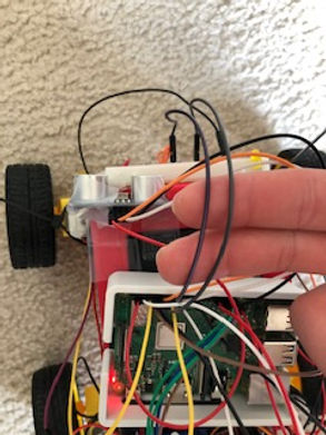
I removed the wires that, in the image to the left, are held in my fingers. They were connected to GPIO pin 23 and 17. They were not necessary to make the program work, and they were not considered into the code. Therefore, I removed them, since they are not necessary.

Current iteration of the headlights, with the breadboard removed.
Video of the joystick control using Blynk. This video illustrates the work done earlier with the joystick controls.

Current iteration of the Phase 3 prototype.
8/3/2021

I am attempting to replace some of the connectors on the headlights with direct wires. I used the wires from the stripped Ethernet Cable (see Low Fidelity Prototype) as a wire to replace the female-to-female wire that connected the resistor to the LED light.
I twisted the wires around the LED light and resistor, and tested with Blynk. Both lights work.


I picked up the new housing unit. I am not yet sure if I will use it.
I did not realize that the housing unit would have a two-tone appearance to it, with black on the bottom half and white on the top half. I am assuming the white material is support material, since the black material is the black ASA material. In my opinion, the two-toned appearance looks good, and is an interesting change to most 3D prints in this course.

Checking the fitment of the mounting holes for the Camera Module Holders. The holes are too small; therefore, they do not fit onto the mounting pinion for the Servo Motor. I will try to enlarge them slightly in order for them to mount properly onto the Servo Motor.


Since the inside hole for the camera module holder did was too small to fit over the Servo Motor my father had the idea of using drill bits to enlarge the size of the hole in small increments. Special thank you to him for the idea.
We started with a size 19 drill bit, and slowly increased the size of the drill hole up to a size 13. Afterward, we reamed the hole with a size 13 drill bit again.
We drilled the hole by hand, but used a chuck as a way to stabilize the drill bit and provide a better grip for drilling.

Setup of the Camera Module on the robot.
Note that the Camera Module does not seat all of the way into the module, but it is still fairly secure inside the holder.


I soldered the wiring connections to the headlights for the positive wire. I did this because the connectors can be disconnected when the robot is driving around, and soldering wires is a way to secure the wires.
Soldering these wires to the resistor and LED also helped me develop my soldering skills.
The first components I soldered are the connecting wire between the resistor and LED light. The resistor was soldered to a length of wire from the stripped Ethernet Cable (see Low Fidelity Prototype). The LED light was soldered to the other end of the wire. This replaced the female-to-female wire where the resistor and LED seated into.
The next step is to connect the resistor to the wire that will be connected to the Raspberry Pi. I removed one end of a short female-to-female wire to solder onto the resistor. This allows me to still connect this wiring setup to the GPIO pin and remove it without any additional steps from before, but the wire still has a hard connection with the solder.


Wiring setup with everything soldered into place.
The next step is to set heat shrink over the soldered connections. This is not completely necessary, but it was a way to make a better solder by adding an insulating material around the exposed conductive metal, which help keeps electricity from flowing into any conductive materials that contact the metal.
The image to the left shows part of the heat shrink beginning to be seated around the wires, with heat being applied to them.

Final soldering setup of the headlights, and the wiring setup mounted to the Raspberry Pi. Note that the white covering is another piece of shrink wrap, which was used to cover over the resistor and exposed wire from the resistor and connecting wire.
8/4/2021

I have decided to convert the robot to the new housing unit. This is because I was not satisfied with the way the motors were seated in place, and the way that the components were not very secure. The image to the left shows how the L298N motor driver seats in the opening. It is not perfect, but more compact and secure than seating it on top of the portable phone charger.
I have to reach underneath the portable phone charger to reach the on/off switch for the 18650 battery pack. The switch also interferes with the top wall that seats in front of it. However, it is slightly easier to use the switch inside the housing than before. This also makes the setup more compact than before.

Overall setup with the new housing unit. Overall, I am impressed with the setup. There are fitment issues with the Servo Motor housing, Ultrasonic Sensor housing and wires for the motors, but it is sufficient for now. The robot still works.
The only issue I encountered was that I set the positive and negative wires in the wrong respective input ports, so the polarity was switched, and the robot moved opposite of the specified controls. I later swapped the positive and negative wires with each port.

I am attempting to add spacers for the Raspberry Pi holder to seat on, in order for me to be able to remove the Portable Phone Charger without manipulating the Raspberry Pi. The image to the left shows the Corian Samples that my father cut into 1/3 strips in order to use as spacers. They will be seated on the housing unit.

Image of the spacers on the robot car. I used double sided tape to secure the spacers to both the housing unit and protective case for the Raspberry Pi.

8/5/2021
I am now working on adding the streaming component to my Camera Module, in order for it to be seen over Blynk. I am using Joseph Petite's project as a guide for the streaming component. Special thank you to him for this.
Attached below is a text file of the source code that Joseph used to stream his Camera Module.
Source: https://github.com/JoeyPetite/Phase-2/blob/main/Video.py
I keep ran into a traceback error on the "class StreamingHandler(server.BaseHTTPRequestHandler):", and ran into an Indentation Error on the "server = StreamingServer(address, StreamingHandler)" command.

I used the other 1/3 strip of the Corian sample in order to create a mount for the Servo Motor. I used double sided tape to secure the Corian to the mount and secure the Servo Motor to the top of the Corian. The opening for the Servo Motor housing is too small for the Servo motor to fit into, so I had to create a surface for the Servo Motor to mount onto.
Current Layout of the Blynk Robot Controls screen. I added a "Video Stream" widget at the top of the screen, and moved the other components to be seated underneath it. I also reduced the height of the Video Streaming Widget as much as I could, in order to keep all components on one screen, and without scrolling. I also shrunk the width of the Ultrasonic Sensor screen and the height of the slider for the Servo Motor in order for these components to fit onto one screen and without scrolling.

I added the IP address for my Raspberry Pi into the address commands in the program. However, this still has not worked. I am not sure how to troubleshoot this issue.
8/6/2021
Video of the robot moving with Joystick control. This is a representation of the joystick controls shown earlier.
Control of the Headlights through Blynk after the headlights were soldered together, instead of being wired through the breadboard.
The problem I rant into was that when I turned on the left headlight, the car would start to move to the left, and the joystick would move left and be stuck to the left without user intervention.
The only way to stop the vehicle from moving afterward was resetting the joystick to its neutral position manually.

I realized that the control for the joystick and the control for the left headlight were both connected to virtual pin V0. Therefore, I replaced virtual pin V0 with virtual pin V8 on the left headlight.

New video of the headlights in operation. The problem is now solved, since the left headlight input does not control the joystick input anymore.
I troubleshooted the Camera Module setup. I tried using LimitOS, both a few days ago at the time of this documentation, as well as today (at the time of this documentation). I did this because I knew LimitOS would work to stream video, since it has throughout the semester. A few days ago, the Camera module worked perfectly fine, but today, the Camera Module does not work. I am not sure what is causing this issue.
Today, I exchanged the Suny connector for two spare connectors, and found out that when I used either of the three, the camera module would not record video in LimitOS. I also used two different Camera Modules themselves, with the same result of LimitOS not displaying video feed. The only things I can think of troubleshooting are the LimitOS code itself, or more likely, the Raspberry Pi itself.
When I take an image through the Terminal Window, the image does not show up in either the Desktop on the Raspberry Pi OS, or the File explorer, depending on the destination of the image.
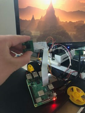

I set up another Raspberry Pi in order to see if the Camera Connector on the Raspberry Pi that I was using was broken. I rant through the installer and set up another SD card to troubleshoot it. I also went through the full installation process. However, when I set up the Camera Module and ran the code in the Terminal Window to take a still image and put it onto the desktop ("raspistill -o Desktop/image.jpg"), the new Raspberry Pi also said that it would not recognize the camera. Therefore, I believe that the Camera Module itself is broken. I even tried using two different Camera Modules and three different Suny connectors.
8/7/2021
I retried capturing an image with the existing Camera Module, as well as the Camera Module with another cable, specifically the shorter cable that came with that Camera Module. I used the "raspistill -o Desktop/image.jpg" command, and tried to capture an image and send it to the desktop.
With the original setup, the image was a black screen. With the new cable attached, the Terminal Window stated that it could not recognize the camera. Therefore, I think that the cable works fine, but the Camera Module is broken. The Raspberry Pi recognized the camera, but the camera did not take an image properly.

I used Joseph Petite's source code, and added it to my multiprocessing code, in order to attempt to add the streaming capability. I saved a copy of the source code, and added the IP address of my Raspberry Pi to the address command. The code compiled and ran correctly, and when I looked at the Camera Module, the LED indicator light was on, but when I ran the code in Blynk, there was an error with streaming. This further proves my hypothesis that the Camera Module itself is broken.
I received a new Camera Module, and tested it on the robot car. When I tested the new camera both through the Terminal Window and LimitOS, the Camera would still not operate properly. The camera would take a picture and video through the Terminal Window, but would not provide live video through LimitOS. I then tried testing both the new Camera Module, as well as the existing Camera Module through the backup Raspberry Pi, and tested the camera through both the Terminal Window and LimitOS. Both Camera Modules worked on both the Terminal Window and LimitOS.
I think the problem is something with the Raspberry Pi, since the Camera Modules were working on the backup Raspberry Pi, but not the current one.


8/8/2021
I tried using a test code, which is on the text file below. I tried using the code to get a preview of the Camera module, but the Camera Module was not shown on the screen when the program was executed.
I tested the preview code (text file below) with the backup raspberry Pi. The code worked this time. However, when I tested it on the original Raspberry Pi, the code did not work, and there was no preview of the camera.
Source: https://projects.raspberrypi.org/en/projects/getting-started-with-picamera/4
Video of the Raspberry Pi streaming through a URL. This is using Joseph Peitie's source code, but I entered the IP address of the Raspberry Pi where the "try: address" command is. I used the new Raspberry Pi.
I tried it earlier with the original Raspberry Pi, but it did not work.
8/9/2021
Professor Fagan claimed that the reason that I could not view the preview on my Raspberry Pi was because I was running the program through VNC viewer, and the camera does not show on the screen in VNC. I attempted to run the camera preview code on a monitor instead, since it should work there. When I ran the program through the monitor, the program worked successfully.
Lessons Learned
1. I learned that it is possible to connect an Arduino to an Internet of Things (IOT) application such as Blynk, it is much more difficult to set up than with a Raspberry Pi. The Arduino is also less capable for IOT applications than a Raspberry Pi.
2. When troubleshooting something, make sure that the power is turned on to all components first. I troubleshooted the Blynk program for moving the robot several times, and spent lots of time on it. Had I realized that the motor drivers needed to be powered on, I would have successfully troubleshooted the project without spending the additional hours of looking at things that were not problematic.
3. 3D printed components (that are not made from industrial materials)are not the most structurally sound parts. I had several parts break from my 3D prints.
4. Pulse Width Modulation control can be used on all GPIO pins for the Raspberry Pi 3B+
5. The Camera Module on a Raspberry Pi can work perfectly fine, but the camera's capabilities can still be compromised if something is wrong with the connecting cable or Raspberry Pi
Sources
1. https://m.youtube.com/watch?v=ZejQOX69K5M
2. https://howtomechatronics.com/tutorials/arduino/ultrasonic-sensor-hc-sr04/
3. https://support.arduino.cc/hc/en-us/sections/360003198300
4. https://support.arduino.cc/hc/en-us/articles/4401874331410--Error-avrdude-when-uploading
5. https://www.arduino.cc/en/software
6. https://www.arduino.cc/en/Guide
7. https://www.arduino.cc/en/Guide/ArduinoUno
8. https://m.youtube.com/watch?v=S2-tcd91BTU
9. https://www.youtube.com/watch?v=IxlwhCe9CtA
10. https://www.elegoo.com/pages/arduino-kits-support-files
11. https://www.youtube.com/channel/UCeb9rinkpNb9VtPyx2fQ_qQ
12. https://www.arduino.cc/en/Guide/Windows
13.https://forum.arduino.cc/t/error-opening-serial-port-com3/401118
14. https://www.arduino.cc/en/Guide/DriverInstallation
15. https://www.youtube.com/watch?v=TNYF72ZrZIw
16. https://www.youtube.com/watch?v=fgzvoan_3_w
17. https://github.com/blynkkk/blynk-library/releases/tag/v1.0.1
18. https://www.youtube.com/watch?v=fgzvoan_3_w
19. https://examples.blynk.cc/?board=Arduino%20Uno&shield=Serial%20or%20USB&example=Widgets%2FTerminal
20. https://github.com/JoeyPetite/Phase-2/blob/main/US.py
21. https://github.com/JoeyPetite/Phase-2/blob/main/ServoPan.py
22. https://joeypetite.wixsite.com/3090/project-design-phase-2
23. https://github.com/JoeyPetite/Phase-2/blob/main/Phase2.py
24. https://grabcad.com/library/tower-pro-micro-servo-9g-sg90-1
25. https://grabcad.com/library/raspberry-pi-camera-rev-1-3-1
26. https://www.youtube.com/watch?v=j-vYta30ovQ&t=30s
27. https://grabcad.com/library/hc-sr04-ultrasonic-sensor-8
28. https://automaticaddison.com/how-to-make-an-obstacle-avoiding-robot-using-raspberry-pi/
29. https://www.maketecheasier.com/capture-scrolling-screenshot-windows/
31. https://www.geeksforgeeks.org/warnings-in-python/
32. https://www.youtube.com/watch?v=xHDT4CwjUQE
33. https://github.com/JoeyPetite/Phase-2/blob/main/MasterCode.py
34. https://www.mathworks.com/help/supportpkg/raspberrypiio/ug/the-raspberry-pi-pwm.html
35. https://github.com/leeinfy/MEGR3090_Robot/blob/main/Phase2Blynk.py
36. https://www.circuitbasics.com/how-to-set-up-the-dht11-humidity-sensor-on-an-arduino/
37. https://www.youtube.com/watch?app=desktop&v=oZ-oFY6TiPw
38. https://github.com/JoeyPetite/Phase-2/blob/main/Video.py
39. https://tutorial.cytron.io/2021/03/16/blynk-video-streaming-using-raspberry-pi-camera/
40. https://www.youtube.com/watch?v=34qj3b6AK4w&t=134s
41. https://randomnerdtutorials.com/video-streaming-with-raspberry-pi-camera/
37. https://pymotw.com/3/socketserver/
38. https://www.raspberrypi.org/documentation/usage/camera/raspicam/raspistill.md
39. https://projects.raspberrypi.org/en/projects/getting-started-with-picamera/3