
Computer Aided Design
With this assignment, students are tasked with creating physical assemblies and components for their Robot Car. Students will use Computer Aided Design software such as Fusion 360 in order to accurately model and design their parts around existing components of the Robot Car.
This is a continuation on the Medium Fidelity Prototype, where more refined materials and design techniques are used to improve the existing prototypes and make them more realistic to a final model.
Assignment Blurb

7/7/2021
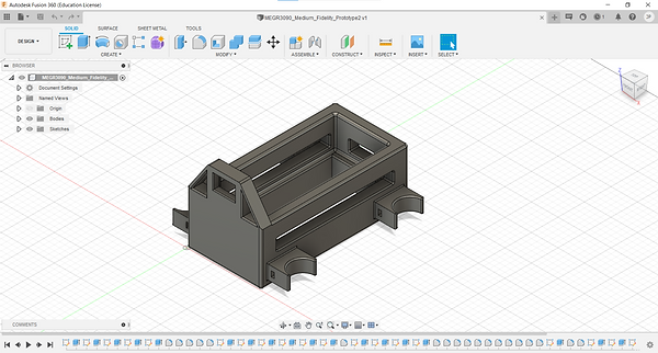
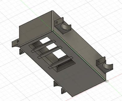
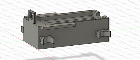
There is already progress on the physical CAD programming in the Medium Fidelity Prototype page. The image below shows the final iteration of the CAD programming up to this point.
Video of the re-setup of the Robot Car. I set up the vehicle again to both make modifications to the vehicle and set up a reference for designing the housing unit and other components.
The vehicle controls are incorrect. Pressing the car forward and backward causes the car to move left and right respectively, and moving the car left and right causes the car to move forward and backwards respectively.

I tried to fix the inverted directions by flipping the GPIO pin wiring for each motor. I swapped the positive wire to the GPIO pin that had the negative wire and vice versa. This did not work, and the car moved in the same direction.
Attempting to swap the positive and negative wires on the output terminals. I placed the positive wire in the terminal where the negative wire was and vice versa. I tried this to change the polarity of the motors. This did not work, and the motors moved the same direction.

I wired both motor controllers to be powered by one battery pack. This removes the need for a second battery pack, which not only makes the vehicle lighter, but also smaller in profile, and ultimately easier to design a space-efficient housing for the components.
Observing the controls of the LimitOS program. The back-left motor is not moving properly when moving forward. I will swap the GPIO pins on the front-left motor to troubleshoot this.
Able to solve the motor direction problem. Swapping the GPIO pins with the respective wires solved the issue. The issue was that the polarity on the motor was inverted.
The car moves slower because of less battery power, due to one less battery pack.
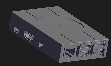
The first order of affairs for structural equipment is a protective case for the Raspberry Pi. I found a model on GrabCad, where users can provide Computer Aided Design files that are accessible to the public. The model I am using is called "Raspberry Pi 3b Case - PlayStation 1" by Cale Teale.
I downloaded the source and will modify the CAD file to fit to my liking. The file is great to use because the dimensions and design around intricate and irregular shapes is already done. The fitment is also usually well-refined. I will modify the outside mostly for aesthetics and to streamline the profile.
Source: https://grabcad.com/library/raspberry-pi-3b-case-playstation-1-1

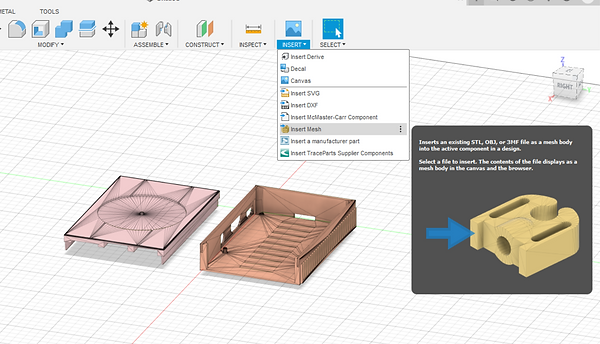
CAD File of the original copy of Raspberry Pi, imported into Fusion 360. The image below shows wherto insert the CAD File. Go to the INSERT drop-down menu, select "Insert Mesh", and retrieve the file that you want to import.

Current iteration of the modifications to the Raspberry Pi cover. I added material on top to cover over the original design and make my own design. The issue I am running into is that I cannot make modifications to the original file directly. I can only add material on top. If there is a way to modify the original file, I will do so because I can make changes much more easily.
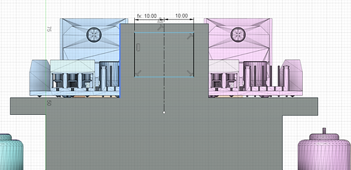
Attempting to redesign the housing unit to accomodate for all of the components. I am using GrabCad files to find models of the components used in the robot car, so I can use them as reference. This will allow me to better design the housing unit and achieve a much better fit on the first print. If they were not available, then there would be a greater chance of some part of the housing not designed properly to fit certain components.
Currently, I am not able to import any component into Fusion 360. This is because most of the files from GrabCad are either SLDPRT, or SLDASM files, while Fusion 360 needs STL Files.
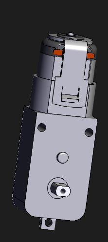
Source for DC motor: https://grabcad.com/library/3-6v-dc-gearbox-electromotor-1
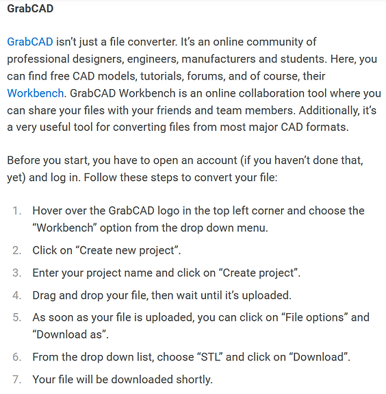
I discovered that, with GrabCad, there is a Workbench program that allows you to re download files as a different file type, such as an STL file. The Workbench was originally made for companies and schools to upload projects, but I will repurpose it as a way to convert files into STL files.
The top image shows where in the Workbench location that the files can be converted, while the bottom image shows the tutorial for converting files
Source for tutorial on converting files: https://all3dp.com/2/sldprt-to-stl-how-to-convert-sldprt-files-to-stl/


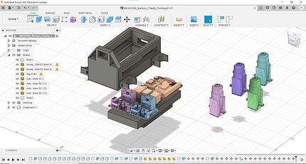
Parts Layout for the Medium Fidelity Prototype. The first iteration is definetly not large enough to house all of the components.
Note: The slender, but longer and wider rectangular-prism component represents the portable phone charger, and the thicker, but smaller component represents the 18650 battery pack. I could not find a CAD model of the specific phone charger that I use
Note2: There are no wires or cables in the image. They will not be shown on the design due to their relative lack of volume and ease of securing out of the way. However, they will not be disregarded in design.
Note3: The camera module nor any sensors are present. I haven't decided which camera module or sensors I am going to use for the final prototype.
I learned how to create a component from an extruded sketch. Fusion 360 associates continuous extrusions as a body, but the body is not able to move. Right click on the body and click "create components from bodies". In order to move the object, select the component from the browser, right click and select "Move/Copy".
I did this initially with the 18650 battery pack to move it underneath the portable phone charger.

Starting to group components together. I first mounted the 18650 battery packs on top of the portable phone charger. Then I mounted the battery pack underneath it.
Initially, I wanted the portable phone charger to be on the very bottom of the assembly. This is because, since the charger is the heaviest component, as well as take up the most area, it would lower the center of gravity of the robot car, therefore making it more stable. However, it would be somewhat difficult to mount the battery pack above it while still keeping a compact profile. I want to make the housing as compact and space-efficient as possible.
I moved the battery pack to be center along the width of the charger, but toward the back along the length of the charger (relative to the initial housing unit). I wanted the phone charger to sit toward the rear of the robot because it should allow for better handling of the vehicle.
This is a similar layout to how the initial housing unit was designed
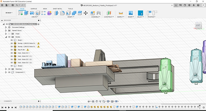
Modification to the components grouping. I added the Rasbperry Pi on top and toward the rear of the grouping (relative to the orientation inside the vehicle). I mounted both L298N motor drivers up front.
I may change this later on because the L298N motor drivers block the USB ports on the Rasbperry Pi.
Note: In the right image, there is an overhang from the Rasbperry Pi. This is because the protrusion for the SD card cannot seat over the portable phone charger without the Raspberry Pi seating at an angle.

Beginning to check the tolerances and fitment on the original iteration of the housing unit with each component. Some tolerance is necessary to ensure that the components will be able to fit into the holes and gaps needed to secure them, and to be able to set them in and remove them without binding. However, if the tolerances are too loose, then the components will experience play and "jiggle", or even fall out completely.
7/8/2021

Checking the fitment of the Portable Phone Charger. The charger definetly does not fit into the proper housing gap. I will have to modify the housing unit in this regard.

Testing how the motors fit into the housing. The motors seat way too low relative to the housing unit, causing the housing unit to be lifted (ride height) way too high.
I initially wanted to have a slightly higher ride height than my Low fidelity prototype, in order to allow the vehicle to traverse over slightly less even and more difficult terrain. However, I overcompensated for this and made the ride height excessively high. I did not have CAD models of the DC motors as reference.
I plan on lowering the ride height by a few inches.
Checking the width of the initial sketch of the housing unit. The extrusion of this sketch makes up the main body of the housing unit. It definitely did not provide enough clearance to allow for a wide enough gap to hold the portable phone charger and have adequate wall thickness.

Importing the images of the measurements of each component from the Medium Fidelity Prototype page. This is a great reference to make sure that I design the housing so that the components fit properly.


Image of measurements for the portable phone charger. The left measurement is the length, the middle measurement is the width, and the right measurement is the depth (or height). This was originally uploaded 6/14/2021.


Measurements of the dimensions of the Battery Pack. The left image is the width, the middle image is the length and the right image is the depth (or height). This was originally uploaded 6/14/2021.

Measurement of the diameter of the neck of the motor housing. This was originally uploaded 6/14/2021.


Measurements of the Raspberry Pi camera module. I will use these measurements for future reference. This was originally uploaded 6/14/2021.
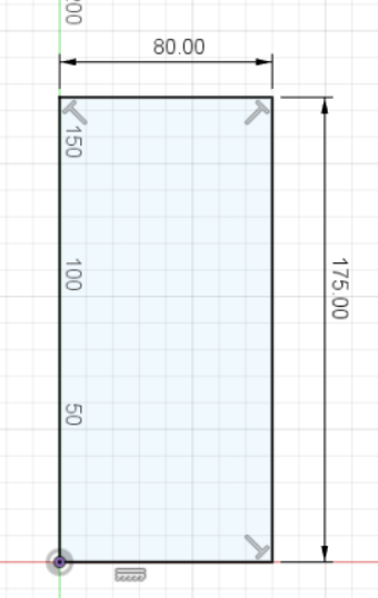
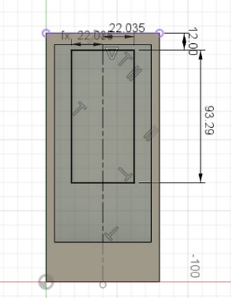
Modification to the initial sketch. I increased the width from 70mm to 80mm. I also increased the length from 140mm to 175mm. I increased the width enough to where I think there will be adequate clearance for the portable phone charger and enough wall thickness for structrual support. I may have slightly oversized the width of the initial sketch, but most likely very little. I will refine this dimension later.
I significantly increased the length of the initial sketch. The main reason is I changed the layout of the components, where the Rasbperry Pi will overhang from the portable phone charger. I wanted to provide enough material for the Rasbperry Pi to seat properly. I may have oversized this quite significantly. I will refine this dimension later.


I modified the way that I dimension the housing gap for the portable phone charger. I originally set the width of the gap to the caliper measurement of the width (see above or medium fidelity prototype), and added 0.1 mm for clearance. This is shown with the image on the left. Now, I added a centerline in the middle of the initial sketch and added two lines on the sides. I added dimensions for both of them. I added a parameter to set both dimensions equal to each other. This is shown with the image to the right.
Note: I did not add all of the lines when I took the right image. The overall sketch is still a rectangle that will have a negative extrusion.
Note: The sizing is not correct with the right image. I will correct this. This is for demonstration purposes.

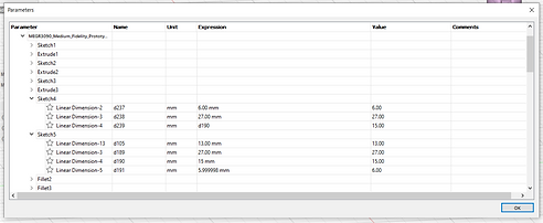
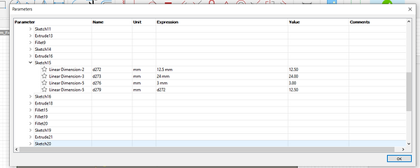
Image of the parameter table for this measurement. I added parameters instead of just set dimensions because I wanted the housing gap for the charger to be centered relative to the overall width of the housing unit. I wanted equal wall thicknesses along both sides of the width. Had I just used set dimensions, if I were to modify the initial sketch, the gap would not be centered.
Note: The sizing is not correct with the right image. I will correct this. This is for demonstration purposes.
An issue that I ran into when changing the initial sketch and housing gap width is that the left-back motor housing unit changed size automatically with the previous changes, which is not something that I want to occur.

The reason that the Motor housing unit increased with the increase in the initial sketch is because of how the dimension for the housing unit was set up. I originally added a dimension between the front-left and back-left motor housing units. This keeps this distance constant, but since the width of the motor housing unit was not defined, this was the dimension that was manipulated. This is shown in the top image
Since the distance between the two motor housing units is not important, I removed this dimension. Since the width of the motor housing unit is important, I did include this dimension in order to define it and keep it constant. This is shown in the bottom image.
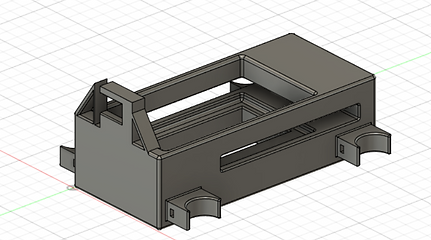
Image of the dimension issue being solved. Now that the proper dimension is in place, the width and height of the motor housing units should remain the same even if the initial extrusion for the motor housing is modified. The distance between the edge of the housing units and the outer edge of the extrusion should also remain the same. However, the distances between the motor housings will change.


I am attempting to add parameters to the dimension between the bottom of the motor housing unit and teh bottom of the overall housing unit. This is to lower the ride height of the robot car by raising the motors relative to the height of the motor housing. The top image shows the original dimension, while the bottom image shows the modified dimension.
Parameter Table for the motor housing units. With this table, I am attempting to make the back-right dimension equal to the front-right dimension. I did this because if I want to modify the height dimension of one motor housing, the dimension of the other motor housing will also be modified without having to manually change the dimensions. This will keep the heights of all the motors even and reduce the risk of the motors being offset and the vehicle being "tilted".
I will attempt to do this with all motor housings.
Parameter Table for the height of the motor housing. I changed the motor housing height for all four motor housings. I did this in order to keep all of the heights relative to the bottom of the extrusion the same. If the height of one motor housing is modified, all four will automatically be modified as well.


I modified the distance between the back of the portable phone charger housing gap and the rear of the entire housing. I moved the portable phone charger closer toward the back in order to shift the center of gravity rearward.

Sizing the housing gap for the portable phone charger. I modified the dimensions around the caliper measurements of the portable phone charger, with a 0.1 mm clearance.
Note: With both images, several features have been removed because I moved the design history bar back toard the first few features. When moving the history bar completely forward, all of the features are present.

Recreating the housing gap for the 18650 battery pack. This time, I am redoing the sketch that creates the extrusion, and along with this creating the proper dimensions for fitment upfront.
I am going to use parameters on this extrusion as well. I used a center line down the middle of the main body, and used a dimension to set a distance from the center line. I used the Parameters table to make the width on the other side equal to the first width. This will create symmetry across the with of the main body along the center line.
I also set the housing further back relative to the main body. I did this to shift the center of gravity backward, in hopes of making the vehicle more agile.


Parameters Table for the battery pack housing gap. I set the width of the extruded rectangle left of the center line equal to the width to the right of it.

3D view of the battery pack housing in the main body after dimensioning and parameters.
Note: I moved the design history bar backward, so not all features are shown.
Removing the openings in the main body. The reason I did this is because of sizing. The openings interfered with the modifications in the sizing for each component. I may add openings later on, but not for the time being.
I originally added the openings for both aesthetics and to reduce the overall weight of the system.
I created a retainer for the battery pack so that it would not fall through. The image on the left shows the dimensions, while the image on the right shows the current final extrusion. This may be subject to modification later on.
The views in both images are bottom views, relative to how the housing unit would be positioned in operation.

Testing the clearance for the battery pack. A 0.1 mm clearance is way too small for the battery pack to seat properly. I may even go as high as 1.0 mm clearance on all sides, since this is not a friction fit and I will need to remove the battery pack eventually.

Resizing the battery pack holder gap. Instead of a 0.1 mm clearance, there is a 1.0 mm clearance. I will test this to make sure that it is not too loose of a tolerance.
After increasing the clearance to 1.0 mm, the clearance appears to be just right. It may be slightly looser than desired, but it should not be enough as to introduce much play into the fitment. However, I may reduce the clearance slightly if it appears to be too loose of a tolerance later on.

Checking the clearance for the portable phone charger. In this instance, the portable phone charger clearly does not fit. I will redo the dimensions of the negative extrusion.

Increasing the clearance of the gap for the portable phone charger. The phone charger definitely does fit into the gap. There is a total of 1.1 mm clearance, up from 0.1 mm initially.

Modified the battery retaining unit. I did not like that the retainer protruded from the bottom of the main body. I reversed the extrusion upward instead, by 3mm. In order to compensate for this, I increased the negative extrusion for the battery pack by 3 mm and increased the extrusion for the main body by 3 mm as well.
Fixing the camera module. With this module, I removed the triangular structures protruding from the edges. While I think these are aesthetically appealing, they serve no other function. I want to make sure that I focus on the critical components that serve a function, and not extras for the time being.

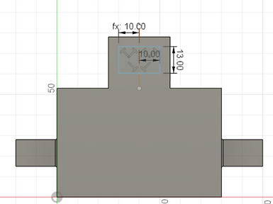
Changing the dimensions of both the outer and inner negative extrusions for the Camera Housing Unit. The top image shows the outer negative extrusion, which will be a recess where the cameral module can seat. The inner extrusion will be a hole that the camera can see through.
I also used parameters in this dimension in order for the recess to be centered along the width of the raised housing unit. The bottom image shows this, where the width dimension to the left of the centerline is the same as the width to the right.


Dimensioning the inside extrusion of the camera housing. I also added parameters to center along the width of the camera housing unit as well. However, I am running into a problem with defining dimensions, since teh overall dimensions are not well-defined enough, but when I add dimensions between the lines and outer edge of the surface, the dimension shows an angle and says that it will over constrain the sketch. I am not sure yet on how to solve this issue.

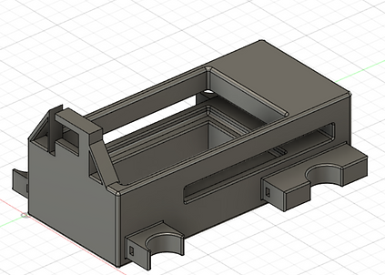
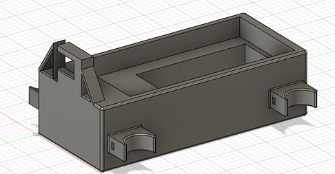
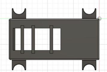
Current housing unit with the components assembled. I will make more modifications to the housing unit, as well as potentially rearranging components to better fit for its intended purposes.
The main challenge is securing the two motor drivers on top of the assembly. They are currently protruding from the edges of the housing unit. They currently sit on top of the portable phone charger. The Raspberry Pi also is not seated properly. I will make modifications to the back of the housing unit to create a more secure mounting setup.
Adding a ledge where the L298N motor drivers overhang from the housing unit. It serves the purpose of addng structural material to support the motor drivers as well as add an attachment point.

7/9/2021
Creating an opening for the SD card and SD card holder on the Raspberry Pi. There needs to be an opening or recess because the SD card protrudes from the circuit board on the Raspberry.
I oversized the opening, so I may make the opening smaller in the future.

I am redoing the inner extrusion for the Camera module housing unit. The first sketch was not able to be extruded. Therefore, I created the second sketch that was better dimensioned. I also used parameters and a center line in order to make the extrusion centered and symmetric about the outer housing unit.

Creating Rounds for different components for the Housing Unit. The upper left image are rounds for the battery pack. The upper right image are rounds for the portable phone charger and the lower-left is the image for the camera housing unit.
The portable phone charger has much larger rounds because the Portable Phone Charger has rounded corners along its length. The rounds in the housing are help the portable phone charger seat more easily into the charger.


Modifying the overhang protrusions for the L298N motor drivers. I shortened the extrusion and remove the extrusion forward of where the camera module is. I did this because it was unnecessary for supporting compnenets and would make the vehicle slightly smaller and lighter. I also added rounds where the overhang meets the main body, in order to reduce the amount of stress on the corners and reduce the amount of edges.


Adding rounds to the bottom (top image) and front (bottom image) of the housing unit. This is for aesthetics and to reduce the number of sharp corners. I may remove them if they affect the supports on the print bed, since this unit will be 3D printed.
7/10/2021

I removed an extrusion from where the 18650 battery pack seats, as shown in the top image. The extrusion looked like it was an initial extrusion for the 18650 battery pack.
When removing it, the enlarged space at the bottom of the 18650 battery pack was removed. There was an enlarged gap, which not only provides some fitment issues, but also provides issues with creating the hole for the wires to protrude from.
As shown in the lower image, the fitment looks to still be good for the assembly.


Deleting the battery pack retaining unit. I removed it because removing the extrusion deleted the opening at the bottom of the housing unit. Since the fitment looks to be proper for the battery pack, covering the bottom of the housing unit is not going to cause the battery pack to protrude into the portable phone charger storage area.
Adding rounds to the bottom of the battery pack holder. This is because the battery pack has small rounds on the edges, and adding the rounds allows the battery pack to seat better in the battery pack holder.

Adding rounds to the inside of the battery pack holder where the wires protrude. I added rounds in order to reduce the chance for sharp edges in the battery pack holder from cutting or damaging the wires from the battery pack. It also provides an easier feeding of the wires through the hole for the battery pack.


Adding rounds to the inside opening of the camera module; both on the edge contacting the camera module and the opposite edge. This will help prevent sharp edges from scratching the module.
Starting to produce the G-Code for the CAD model. The GCode software the class is using is provided by Makerbots, which

In order to make an STL File of the model without including all of the reference components (ex. DC motors, Raspberry Pi, etc.), I created a new file of the same model of housing unit but removed all of the reference components. This will allow the G Code to be produced without the reference components.
The issue with this approach is that if I want to make changes to the original model in the future, I would have to create a new file and delete the reference components repeatedly.
Inserting the STL file into the GCode file. The housing unit appears to be close to the absolute maximum size on the print bed. This may be an issue later on with printing the component if there are any overhangs outside of the print window.
One thing I am surprised about is that there are no layer breakdowns or scroll bar to analyze different layers. I also do not see infill options either. These are common features on PrusaSlicer, which is another Slicing software that I am more familiar with, since I used it throughout a previous course.
Current Application Settings for the G Code. I am still using millimeters as the Application Units because the CAD program used millimeters as its main unit, and I wanted to maintain as much consistency across the project as possible.
In regards to Quick Settings, which allow users to change layer height, number of perimeters (shells), and infill percentage. I modified the Infill percentage from 0.1 to 0.2, or from 19% to 20%. I increased the infill because the housing unit is subject to significant impact from bumping into objects, as well as having to sustain the load of the vehicle components. Increasing the infill will make the housing unit more resilient against these and other loads.
7/11/2021
I was referred a source for the reference part for the 18650 battery pack holder from Nick Corvera. The reference part is greatly appreciated.
The image to the left shows the battery pack reference part alongside the extruded sketch used to represent the battery pack. The extruded sketch is slightly longer and wider than the imported STL file, but they are roughly the same height. The main profile difference between the two models is that the imported STL file has rounded edges, while the extruded sketch does not. Overall, the imported STL file has all of the intricate details, including the on/off switch and locking clips, while the extruded sketch is a simple rectangle.

Checking the fitment of the imported STL battery pack to the battery pack holder. The fitment is somewhat looser than the extruded sketch because the length and width dimensions are smaller with the imported STL file, and the rounded corners gives the appearance of a smaller profile.
However, I will keep the dimensions the same because the battery pack has an on/off switch and catch mechanism that protrudes from the main body of the battery pack. The housing unit needs extra space along the length dimension to add clearance for the on/off switch.

7/12/2021
Week 8 Agenda Blurb


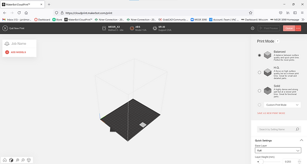
Starting to print the first physical iteration of the housing unit. The image above shows the G-Code preview for the print. I restarted the print Queue, so I used diffrerent Quick settings than the previous G-Code iteration for this project. The following settings are shown below:
-
Base: Raft
-
Layer Height: 0.23
-
Infill: 0.2 (20%)
-
2 Shell Perimeters
-
Breakaway - model material
-
-
-
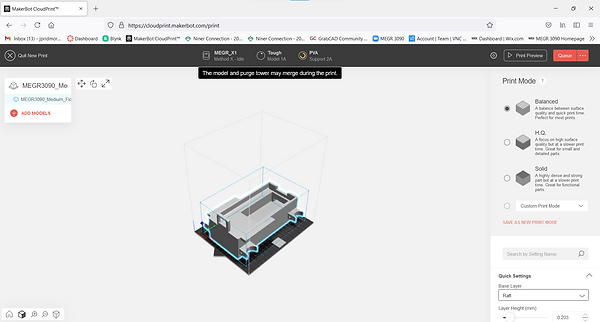
I am attempting to use the ASA print material with --- support material. I want to try the ASA material to see if it has better physical properties than ABS or the "Tough" material that are in the other Makerbot Printers on hand. Apparently, ASA has UV resistance, which is not particularly useful for this application ftu would be useful in applications where the material is exposed to lots of sunlight.
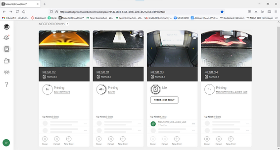
The above image is the print Queue for the Maker bot Printers. My print is the right-most Queue window with the red filament. The image shows a current or very recent snapshot of the progress of the print. Not only is this very interesting, but it also is useful for checking the relative print progress as well as checking for any defects and failures. It is more realistic and visual than using sensors or software to check for any problems with printing.
Attempting to insert the DC motor reference files as STEP Files into the model. As discussed in class, the STEP File allows the items to be inserted with their respective colors, instead of a solid color. It also allows the file to include its edit history. This is very useful if you want to include certain features from the inserted file into your designs.
The STL file treats an item as a body, which is a solid physical being. A STEP File treats the item as a component, which can be a combination of multiple solid physical beings. This allows users to edit and observe its design history. It also allows the individual bodies to be physically distinguished and have their own colors.
I attempted to use the upload command in the file window to upload the STEP File into the CAD File. This does NOT work.
Lessons Learned:
1. GrabCad's workbench program is able to download files from GrabCad as multiple different types of files- including STL files
2. You can turn continuously extruded sketches into components that can be moved, in Fusion 360
3. Create a proper naming convention for components in your design. Without a way to identify what youre trying to explain, describing and documenting your progress can be very confusing and complicated.
4. Sizing components and coming up with an arrangement of parts that will work takes the vast majority of design time
5. It's difficult to make a perfect mechanical design in one 3D print iteration- usually you will run into problems that require multiple prints
Sources
1. https://grabcad.com/library/raspberry-pi-3b-case-playstation-1-1
3. https://grabcad.com/library/3-6v-dc-gearbox-electromotor-1
4. https://all3dp.com/2/sldprt-to-stl-how-to-convert-sldprt-files-to-stl/
5. https://grabcad.com/library/l298-dc-motor-driver-1
6. https://grabcad.com/library/3-6v-dc-gearbox-electromotor-1 -- Motor NOT used: unable to convert file
7. https://grabcad.com/library/raspberry-pi-3b-with-sd-card-1
8. https://grabcad.com/library/geared-dc-motor-for-arduino-applications-1
9. https://www.autodesk.com/products/fusion-360/blog/components-bodies-for-new-designers/
10. https://drive.google.com/drive/folders/1YxKF2knd0AccAUbueLLcAKX4sRc76Lrq
11. https://www.youtube.com/watch?v=QI30XvBymgA&t=316s
Special thank you to Nick Corvera for the STL File for the 18650 Battery Pack