
Introduction to Python
With this assignment, students are tasked with completing projects that utilize Python programming language. Students will use the Raspberry Pi and electronics components such as LEDs, motors and buttons.
Assignment Description:

What you will need:
-
DC Motor
-
Stepper Motor
-
Servo Motor (SG90 recommended)
-
Breadboard (half-breadboard or larger)
-
Male-to-male jumper wires
-
Female-to-female jumper wires
-
Male-to-female jumper wires (optional but recommended)
-
Raspberry Pi
-
L298N motor driver
-
ULN2003APC motor driver
-
Thonny IDE Python host
-
Push buttons
-
Jumper wires

Raspberry Pi 3B+ GPIO pin Schematic
Source: https://www.jameco.com/Jameco/workshop/circuitnotes/raspberry-pi-circuit-note.html
6/16/2021
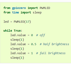
Video of LED with modified PWM code. I changed the LED output values to increments of 0.2; therefore, I added three more iterations of the LED in the while loop. I also changed the time iterations to vary from 0.3 to 1.8 seconds, in intervals of 0.3 seconds.

Setup guide for the Button Python project.
Source: https://gpiozero.readthedocs.io/en/stable/recipes.html#keyboard-controlled-robot
Video of the Button Python project according to the Python recipe's list. It is close to identical to the project according to the list, so I will make modifications to this project.
Note: I left the Raspberry Pi and its components attached to the prototype robot car. I did this because work is still being done on the vehicle, and I did not want to hinder its progress.
Modification to the button program. The only difference with this program is that instead of the print commands being "Button is pressed" and "Button is NOT pressed", they are instead "Yay!" and "NOOOOO!" for on and off, respectively. (on being the button is pressed, while off being the button is NOT pressed).
More modifications may be made to the program later on.
Setup guide for the Button controlled LED Python project.
Source: https://gpiozero.readthedocs.io/en/stable/recipes.html#keyboard-controlled-robot

6/17/2021

Video of Button Controlled LED project. It is close to identical to the project according to the list, so I will make modifications to this project.
The breadboard and Raspberry Pi setup are still in the housing of the robot car prototype, and will remain so unless the vehicle is disassembled.
Videos of the modified Button Controlled LED project. I incorporated code from the button project, LED with variable brightness project and Button Controlled LED project. I utilized PWM values from the variable brightness project in order to change the brightness of the LED. I utilized the while loop, if and else statements from the button project in order to incorporate the button into the project. Since the project utilizes PWM values, I could not have just used the button.when_pressed and button.when_released commands that were used with the button project, since they cannot consider the varying input values for the LED.
I originally tried to use the button.when_pressed and button.when_released commands at first. However, the LED would not turn on when the button was pressed. I also did not import enough commands. At first, I tried to utilize commands from the original LED project, but forgot to import all of the commands from gpiozero. I later incorportated the PWMLED command from the variable brightness project, and project worked.
I am still running into difficulties when the button is released. The LED still runs through its commands as though the input from the button was on, even though the button is NOT pressed.


Source codes for the Button Controlled LED, LED with Variable Brightness and Button projects respectively
Source: https://gpiozero.readthedocs.io/en/stable/recipes.html#

When using one of the 5V power sources on the Raspberry Pi, I ended up burning some of the input ports on my breadboard. I do not exactly know what caused this to occur, but I am speculating that either the male-to-male wire from the Elegoo kit is receptive to heat and got very warm, the GPIO pin induced a lot of heat when introduced to electrical power, or the unit itself that sends electrical power to the GPIO pin was overheated.
6/19/2021

Current wiring setup for the motors controlled by Buttons project. I am almost complete with wiring, but the programming still needs to be done. I added an L293DNE motor controller from an Arduino Uno starter kit instead of an sn754410 motor controller because I was not able to find the latter. I will attempt programming this to see if they are similar enough for the project to work.
Schematic of the Button Controlled Robot Project
Source: https://gpiozero.readthedocs.io/en/stable/recipes.html#

6/20/2021
I learned from an Arduino form that the L293D and SN754410 motor drivers are quite different. The latter driver is an "upgraded" version of the former. The SN754410 can support about 400mA more current through it than the L293D. This may be an issue with running the motors, especially 2 motors at the same time.
However, both motor drivers should have similar pin setups, so the wiring setup should be almost the same, if not identical.
I have been running into new issues with setting up the VNC viewer and server setup on my computer. When I sign into the server, and access the Raspberry Pi's IP address, the connection window will load for a long period of time, and say "Timed out waiting for a response from the computer".
I have done several things to troubleshoot the problem. Initially, I thought it was that the portable phone charger ran out of battery (it did not), so I charged it fully. When that did not work, I thought it was the connection between the power source and Rasbperry Pi. I replaced the portable phone charger with a micro usb cable plugged into a wall (110V outlet). The same problem still occurred, despite the red light inicator for power being on during both instances. I eventually just ran a non-headless setup with a monitor and connected keyboard and mouse.
6/21/2021
Video of the button LED program, but programmed with a class.
Note the "def" command in the script. The def command allows the user to define a certain name of a variable, and associate commands in regards to it. However, the def command cannot be associated with numerical values, only names of variables that you want to define.

Picture of the initial button controlled robot setup. I am planning on changing the project, since the project does not require two motors and 4 motors. I am also changing the setup because it is possible to use the L298N motor drivers, which I have more experience with.
This will ultimately simplify the circuit setup and allow me to focus on programming than wiring and electrical setup.

Current setup of the Button Controlled Robot project. Note that there are no push buttons currently on the system. That is because I am currently using a tutorial that does not include the push button, and the motor will run on its own. I changed tutorials because I needed to incorporate the L298N motor driver into the system so that it could deliver extra power from the 18650 batteries. I will also add a push button later on.
The schematic below shows the setup

Schematic of the new setup. There are a few modifications that I will make, including using two, 18650 batteries instead of a 9V battery.
The issue that I am running into is administering power to the motor driver. For some reason, when I attach the battery pack both according to the above schematic and directly into the motor driver itself (see Low Fidelity Prototype), the motor controller indicator light does not turn on. I have attempted this with two motor drivers, so I am ruling out that the motor driver is not working. I also connected the battery pack directly to a motor to test it, and the motor runs. Therefore, the battery pack works. I assume it is because the leads on the battery pack are not long enough to fully contact the connection input points on the motor driver.
After attempting to administer power through the battery pack into the Raspberry Pi, the problem is not that the wire leads on the battery pack were too short. I connected the wire leads on the battery into female-to-female wires and connected those to male-to-male wires. I attempeted another motor test while using the ends of these wires and the test was successful even though all of the additional wiring. I secured the wires into the 12V input and ground respectively. The conductive leads on the male-to-male are more than long enough to properly contact the ports on the motor driver.
6/22/2021
I was able to administer power to the motor driver.
I first attempted to administer power using two different battery packs. In both instances, neither pack worked. Later, I tested the battery pack on one of the motor drivers on my robot car, since I knew that the motor driver worked. In this instance, no power was administered to the driver either.
I then replaced the batteries with some batteries that were in use with the Low-Fidelity prototype, since I knew they would be able to administer power to the motor driver. When I set them in the battery pack used for this project, I was able to administer power to the motor driver that was on the robot car.
However, power was still not administered to the motor driver used for this project. To solve this, I replaced the motor driver with a new one. After this, the new motor driver worked.
The motor is still not running yet, but power is administered to the motor driver.

Current setup with motor driver working.

Error code with the current programming. The GPIO.setup commands are either invalid or already in use. The program attempted to continue anyway, but that did not solve any issue or make any progress.
I ran a modified version of the program from the motors project on the Basic Recipes list. I changed the GPIO port numbers in the program from 4 and 14 to 26 and 20, respectively. I did this because, in theory, the motor should be able to run, since the motor driver should not require special programming.
When I ran the program, I did not encounter any warnings in the shell, but nothing happened. The motor was not powered on.
Successful setup of the motor program. With the previous iteration, I realized that the power source for the motor driver was not turned on. I turned the battery pack on, and the motor initially began to move, even with no Python program running. This is normal, since there is nothing interrupting current going to the motor. Adding a button should provide this.
Video of the modified code for the Motor project. Instead of the motor moving "forward" for 5 seconds and "backward" for 5 seconds (quotations because those directions are relative; the motor moved the opposite direction), the motor moves forward for 2 seconds, backward for 2 seconds, forward for one second and backward for 1 second.


Code for the motor projects. On the left is the code from the GPIO Basic Recipes list that was modified to be compatible with this motor setup. On the right is the modified code afterwards to make the motor change directions more often.

Adding a button into the circuit for the motor project. On the left is a video of power administered to the motor driver without running any Python software through. On the right is a video of power administered to the motor driver with the final modified motor code.
The button setup is purely electrical, since the button only opens and closes the circuit. I cannot control the button through Python with this setup. Therefore, the button can only act as an on/off switch, and not run an iteration of program from beginning to end on its own.


Codes and respective source codes for the Servo portion of the motor project. These are the first iterations of code that I am attempting to use. Neither program utilizes a button yet. The left code allows the motor to move in continuous but very small increments (creep). The right code programs the servo to move to the "minimum", or one extreme on the end of its rotation, move to the midpoint of its range of motion, then move to its "maximum", or other extreme on the end of its rotation.
Source: https://gpiozero.readthedocs.io/en/stable/recipes.html#
.jpg)

Running into issues with both programming, and mechanical disassembly of the servo motor. On the shell, I ran into a statement saying "To reduce servo jitter, use the pigpio pin factory". I do not know how to utilize this yet, if I end up needing to use the library. The source codes for all of the servo projects on the GPIO basic recipes list do not require this library.
I disassembled the servo motor because it was moving at the end of its range, and I do not know how to electrically, or by using software, reverse the direction of the motor. I disassembled the motor and moved the gear back in order to give the servo a greater range of motion. I am surprised how low of a gear ratio the motor has. It helps the output have more torque, at the expense of angular velocity.
6/23/2021
I discovered that, just like with a DC motor, if you switch the polarity on a servo motor, the motor will spin the opposite direction. I attempted this when using a servo motor program. This does not work when you incorporate code used for DC motors.
I am still not yet able to program a set position on the motor controller. I can only make the servo move continuously. This can pose an issue, since servo motors usually can only travel a certain range of motion, not a full 360 degrees like most DC motors. My servo is mechanically limited by this, so components can bind, which adds wear to the motor.


I am now moving on to setting up the Stepper motor project, since I could not troubleshoot the issues with the stepper motor. Instead of the L298N motor driver, I am trying to use the ULN2003APC motor driver from the Elegoo Uno R3 Kit. This driver is made specifically for the stepper motor. The first motor driver does not work because there are only 2 inputs for the motor, while the stepper motor has 5 wires. It requires a special motor driver. The project also may not need the additional power from the 18650 batteries.
I am running into the issue from the picture to the right. With this program, the GPIO.setup and GPIO.output commands are not valid for the Raspberry Pi using Thonny IDE. The source code was made using a different host application.
Source code for the Stepper Motor project. The modification I made from the original code were the GPIO pins from the Control_Pin command in line 6. instead of GPIO pins 7,11,13 and 15, I used 6,13,19 and 26 respectively.

Attempting to use another code for the Stepper motor. This code may also not be compatible with Thonny IDE, because I am running into syntax errors. This could be an issue with the version of Python that I am using, or simply input error, but I have ran into issues with the last source code, so they may have a common source of error.
Source: https://bitbucket.org/MattHawkinsUK/rpispy-misc/raw/master/python/stepper.py
Introducing power to the motor driver. DO NOT ATTEMPT THIS! When I plugged in the power source, there was smoke emmitted from the motor driver, and a burning smell. I possibly damaged or destroyed my motor driver because of it.
I will try to find a better way to administer power if need be. I attempted this just in case there wasn't enough power delivered from the Raspberry Pi to the Stepper motor.

Running the Stepper motor code. I copied the code from the source code instead of manually typing it out. I added parenthesis around some of the print commands in order to follow proper syntax. This helped correct any discrepancies in typing it. The various arrays run in sequence in the shell, and the print commands print the certain GPIO pins. However, the motor still does not turn.
Running the code directly onto the Terminal Window. This is another method of running the code, which I wanted to attempt in case there were differences between Thonny and another host. The image below shows what to input into the Terminal Window.
Source: https://www.raspberrypi-spy.co.uk/2012/07/stepper-motor-control-in-python/

Video of delivering power to the motor driver. Instead of using a battery pack, which oversupplied power, I used power from the Rasbperry Pi itself, which was enough to power the stepper motor.
I plugged in the positive power input terminal (red wire) into one of the 5V power sources on the Rasbperry Pi. I plugged the negative power input terminal (white wire) into one of the ground ports.
Running the stepper motor with the source code. The motor moves in a similar fashion. However, when only the power is enacted, the motor moves in a continuous fashion, similar to a DC motor. When the code is enacted, the motor moves in "jerky" steps, trying to find the correct step to land on.
Note the transition of the LEDs on the motor controller. This stepper motor is half-stepping, where the magnetic field moves from one coil, then moves halfway to the next coil (magnetic field is enacted on two coils), then the next coil. This is why you see part of the LED light up when moving onto the next iteration, instead of the LEDs lighting fully and sequentially.
Using a clip as an indicator of movement. Note that when the code is compiled and ran, the motor moves in the "jerky" movements, trying to find the proper step.

On the left is the setup I used to include the button into the system. Essentially, I used a breadboard with a button. the positive power input was connected to a male-to-male wire (since I do not have female-to-male wires) and connected by the first end of the button. I then added a male-to-male and female-to-female wire on the following end of the button and connected this into the 5V power pin on the Rasberry Pi.
I am now continuing the Servo motor project. I am using a tutorial from the video on the left. Currently, I have connected the servo direclty to the Raspberry Pi as shown in the middle. I am still having issues delivering power to the servos. I have switched the servos from the one in an old Arduino kit (black) to the SG90 motor in the Elegoo Uno R3 kit (blue).

.jpg)
6/24/2021
I just began to set up an account for Blynk, which is another Internet of Things (IOT) application for electronic devices such as Raspberry Pi. At a first glance, it seems more in-depth than Limit OS, but more complicated to use. However, it most likely is easier to use than setting up an entire Internet of Things system through purely Python programming.
However, the image below read that the WIFI Provisioning is NOT yet compatible with Rasbperry Pi. This may be an issue with setting up a Raspberry Pi as a device that can be used on Blynk.


import RPi.GPIO as GPIO import time servoPIN = 17 GPIO.setmode(GPIO.BCM) GPIO.setup(servoPIN, GPIO.OUT) p = GPIO.PWM(servoPIN, 50) # GPIO 17 for PWM with 50Hz p.start(2.5) # Initialization try: while True: p.ChangeDutyCycle(5) time.sleep(0.5) p.ChangeDutyCycle(7.5) time.sleep(0.5) p.ChangeDutyCycle(10) time.sleep(0.5) p.ChangeDutyCycle(12.5) time.sleep(0.5) p.ChangeDutyCycle(10) time.sleep(0.5) p.ChangeDutyCycle(7.5) time.sleep(0.5) p.ChangeDutyCycle(5) time.sleep(0.5) p.ChangeDutyCycle(2.5) time.sleep(0.5) except KeyboardInterrupt: p.stop() GPIO.cleanup()
Attempting a new tutorial with the servo motor. The setup follows the wiring schematic on the left and the source code on the right.
I attempted one iteration of the tutorial, but the motor still is not rotating. There is a possibility that there is not enough power being delivered to the servo, since the code compiles perfectly fine, and the GPIO pin setup is accurate. However, with other tutorials, others have been able to run the motor without an external power supply, so my assumption may be incorrect.
Sources for both: https://tutorials-raspberrypi.com/raspberry-pi-servo-motor-control/
Running a successful iteration of the servo project from the new tutorial. The only issue I ran into was that I incorrectly plugged in the voltage input and control signal wires. I just swapped the wires and they worked correctly.
Incorporating a button into the servo motor setup. I removed the wire from the voltage input on the servo motor and added a button as an interrupt on the breadboard. I took a male-to-male wire and attached it to the lead side of the button. After attaching the button to the breadboard, I added a male-to-male and female-to-female wire wire setup that connected the following end of the button to GPIO 17.

Setup of the servo motor projects. On the left is the setup without the button. On the right is the setup with the button.


A third iteration of the Button project. I modified the code even more by adding wait commands after each print, and added multiple print commands. On the left is the video of the modified Button Project in operation. On the right is the code for the project.
6/26/2021
Attempting to add a button component in the software, but without success. The above video are the current modification to the source code.
6/28/2021
Attempting to install and use the Blynk application for my Raspberry Pi projects. As stated earlier on this page, Blynk is an Internet of Things (ioT) application for cell phones and computers, so it allows a user to control a device such as a Raspberry Pi on another device through the internet. Blynk is similar to LimitOS, but has more extensive capabilities, and is more complicated to use. You can incorporate, for example, various motor speeds, which you cannot do with LimitOS.


The image on the left shows the setup on the setup screen before running the program. The setup scren uses electronic components, and associates them with certain GPIO pins or input/output settings. The middle screen shows the setup for the button module. The "GP4" shows that the button is to be manipulated through GPIO pin 4. The push or switch allows the button to click once for "on" and once for "off", or you hold the button down for "on" and release it for "off", respectively. The image on the right shows the LED module. It does not have a GPIO pin setup since that controls the button, and the button controls the LED. However, there is an input from the button that is associated with "V0".
Here is an iteration of the LED project using Blynk (see above). I downloaded the application on my cell phone; originally downloading the "Blynk new ioT" version, then downloading the legacy version. I attempted to set up the project on both versions, but only the legacy version worked.
I do not yet know how to record the LED turning on and off while screen recording the button setup at the same time.

Schematic of the Button Controlled LED project using Blynk.
Source: https://bc-robotics.com/tutorials/getting-started-blynk-raspberry-pi-3/
6/29/2021
After shutting down power and the terminal window, I attempted to restart the Button Controlled LED project to allow the Blynk application to replicate the previous iteration of the project. The issue that I encountered was that just accessing the application on my phone did not allow the project to run, nor did just entering the authentication token into the terminal window. I had to go through almost the entire tutorial, with running all of the commands in the terminal window. This may not be necessary, but it is a path that will work for this project.
I attempted two things with the LED project to see what would occur. I attempted to bypass the button by using a jumper wire. When I set up the program, the Button moule on Blynk still worked as if it were an electrical button. Therefore, all of the control of the button is in software, and nothing on the control of the button is mechanical or electrical. Of course, this is not ideal for situations where you want to prevent current from flowing through a circuit and preventing damage to components, but it will work for this project.
The other thing I attempted was to replace the LED with a DC motor to see if it would run instead. The motor did not run. I am not sure if the software limited the current passing through the LED which was inadequate for the motor, but regardless it will not work for a DC motor.

Setup of the Button Controlled LED project with the jumper wire used as a bypass.
6/30/2021
Attempting to use Python in conjunction with Blynk to incorporate separate Python commands that are not created by the Blynk software. This also allows me to run a Blynk project without restarting the commmands in the Terminal Window (see above). I had to update the Python that was being used, which was set originally at 2.7.4. I updated it to 3.7.3.

I am currently running into errors with the Blynk Library. The first command that the source code executed was "import blynklib", which allows the code to use certain commands from the Blynk Library. However, there is an error that says "no module named 'blynklib'".
During the 6/30/2021 class session, there was troubleshooting with setting up Python and the Blynk Library. However, the troubleshooting did not fix the restriction on importing the Blynk Library.
I ran through the tutorial for installing the Blynk Library, but still to no avail.
tutorial: https://github.com/blynkkk/lib-python
I attempted to install Python 3.7.0 onto my Raspberry Pi OS. however, after I extracted the Python from the source and attempted to create an alias, I ran into issues with getting Version 3.7.0 extracted. I do not know what the issue is with this.
The reason I tried to install Python 3.7.0 is because I think (but I am not certain), that this version is necessary for running the Blynk software and importing the Blynk library. The host may not recognize the Blynk library because the version of Python I have on my Raspberry Pi OS is 2.7.16, which may not be a recent enough version.
7/1/2021
I set up the original Blynk LED project again, to see if I could replicate the results (and because I know that the results work). I tried to copy the terminal window commands for betim.
I had to change the polarity of the button switch in the Blynk phone application. The issue was that when I pressed the button to "on", the LED would turn off, and when pressed "off", the LED would turn on. As seen below, the GPIO pin 4 output changes from 1 to 0 instead of 0 to 1 like the original setup. I do not know if this is a section of the circuit that has flipped polarity, or if it something else. I do know that the LED has correct polarity because if the ends of the LED are switched to the incorrect position, the LED will not turn on.
Another issue that I ran into was that when I plugged the wire from the negative terminal on the breadboard into the ground on the Raspberry Pi, the Raspberry Pi would turn off, and I would have to restart the process.
When I reinstalled the button instead of the jumper wire bypass, the LED would not turn on unless the button was pressed. This was different than the first time I started the project, when I could
I still am running Python 2.7.16, which may not be a recent enough version to run the project through Thonny IDE. I will continue to troubleshoot the update for Python, but at the moment, running commands through the terminal window is the only way to run the Blynk projects. This is very time-consuming relative to running the program through a Python host.

I am trying again to install Python 3.7.0, but without success. I went through the entire list of Terminal Window commands from the tutorial. When I finish the tutorial, and use the python -V command (to view which version of Python I have on my Rasbperry Pi), the Terminal Window says version 3.7.0. However, when I open a new Terminal Window and use the same command, the version stated is 2.7.16. I don't know why this still occurs, since I ran through every command prompt, so the Python should be installed on the system. The Terminal Window even states that version 3.7.0 is the recent version. The only challenge is that this is not reflected in a new Terminal Window.

Attempting another iteration of setting up the Blynk Library. I have already done this, but wanted to do it again in order to see if it was not installed properly or there is a problem associated with it. I believe that this could be the reason that I run into the "no module named 'blynklib'" error when running the LED project through Python.
As the image to the left shows, I ran the command to install the Blynk library (first command). It says that the Requirement was already satisfied. However, when I run the setup test program, it says "can't open file 'setup.py'". This could be an issue related to when I run the Python program.

I attempted to manually enter the Blynk Library again. The issue that occured is that the "python setup.py egg_info" failed with error code 1, as seen with the image to the right.
7/2/2021
I attempted to install a later version of Python through the Python main website. however, I do not know if the files are compatible with the Raspberry Pi. I did not work through the entire process because I did not know if they would work
I am still continuing to troubleshoot the Blynk Library not being recognized by Thonny IDE.
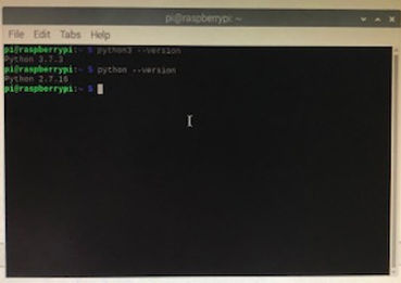
As shown to the left image, I discovered that, when I type "python3 --version" into the Terminal Window, I see that I have version 3.7.3. When I just type "python --version" in the Terminal Window, I see version 2.7.16. I do not know why this is. I do not know if I have both versions installed on my Rasbperry Pi OS, or if the Python version 3.7 is installed with certain applications such as Thonny, while version 2.7 is installed for the rest of the applications?
I am also still wondering if this is the source of my error for importing the Blynk Library? I may rule this source of error out, if the Thonny IDE recognizes Python 3.7.3. However, I cannot eliminate it for certain because it still shows version 2.7.16 when I type the second command, and the program may recognize this version.
On the shell for Thonny IDE scripts, it says Python 3.7.3, or the file (/usr/bin/python3).

I realized that when I was installing the Blynk Library onto my Rasbperry Pi os, it was installing under version 2.7.16. The Thonny IDE was running Python 3.7.3. Becasue of these differences, the Blynk Library wasn't recognized under the more updated version of Python, and therefore not recognized by Thonny. I attempted to redownload the Blynk Library under Python 3.7.3.

I attempted to reinstall Blynk Library using "python3" commands insead of "python" commands. There is an error message saying "Could not install packages due to an EnvironmentError". I could not install the Blynk Library onto Python 3.7.3 with these commands

Attempting to redo the installation process for Blynk Library. I found out that instead of using python3 commands, you need to install pip3 commands when installing the pip. This was successful.
I redid the installation process, including using "sudo apt update && sudo apt upgrade"

I also ran into issues with the Python script provided to us for the LED project. The libraries that you import are case sensitive. The original version used "import blynklib" to import commands from the Blynk Library. However, you need to use "import BlynkLib" because the Blynk Library uses capital letters for the first "B" and second "L".
I had to correct this for both "import blynklib" and "blynk = blynklib.Blynk(BLYNK_AUTH).
Note: I changed the GPIO pin on the led variable. This is because the input wire was connected to GPIO pin 4 from past projects. For convienence sake it was easier to wire to GPIO pin 4 instead of pin 25
Source: https://peppe8o.com/personal-iot-with-blynk-on-raspberry-pi/

I also had to remove "@blynk.handle_event('write V3')". This command may be necessary in the future, but it is not necessary to make the program run. I had to remove it because there was an AttributeError stating "'Blynk' object has no attribute 'handle_event'". I commented the command.
Successful iteration of the Blynk LED proeject. Here is a video (with my dad being the cameraman) of me pressing the virtual button in the Blynk Legacy app and observing the LED turning on and off.
Note that this virtual button is a software controlled button, not a physical button wired electrically to the circuit, as observed by the yellow bypass jumper wire.
7/4/2021
I found 2 tutorials for using Blynk with the ultrasonic sensor, sourced below:
Source1: https://tutorials-raspberrypi.com/raspberry-pi-ultrasonic-sensor-hc-sr04/
Source2: https://www.pcbway.com/project/sponsor/UltraSonic_Level_Sensor.html
7/5/2021
Continuing with the Ultrasonic sensor. I used Source1 (Raspberry Pi webpage) from yesterday's tutorials.
The primary change I made today was directly copying and pasting the source code into Thonny IDE instead of typing the commands while looking at another screen for reference. This helped to eliminate a source of error by typing the commands. I recommend this practice, or downloading the file directly onto the host, if possible.

Schematic of the Ultrasonic Sensor Tutorial using the Tutorial from the Raspberry Pi webpage, as well as images of the physical setup below. Note that the GPIO pins for the Raspberry Pi are different in the physical setup versus the schematic, because they are two different Rasbperry Pi models. The schematic shows the model B, while I am using the model 3B+
Source: https://tutorials-raspberrypi.com/raspberry-pi-ultrasonic-sensor-hc-sr04/


Video of the ultrasonic sensor using Python programming.
Note two things:
1. This is only using Python programming, not Blynk. This is a great start, in my opinion, because it ensures that all of the components work properly and provides a basic seup. However, I will continue to make changes to incorporate Blynk into the project.
2. The readings seem very inconsitent and sometimes inaccurate relative to the distance of my hand. This is because the wires and resistors connecting the Ultrasonic Sensor to the Raspberry Pi are in front of the wave transmitter. I plan on turning the sensor around and rearranging the wires to allow the sensor to have an unobstructed view.
#Libraries
import RPi.GPIO as GPIO
import time
#GPIO Mode (BOARD / BCM)
GPIO.setmode(GPIO.BCM)
#set GPIO Pins
GPIO_TRIGGER = 18
GPIO_ECHO = 24
#set GPIO direction (IN / OUT)
GPIO.setup(GPIO_TRIGGER, GPIO.OUT)
GPIO.setup(GPIO_ECHO, GPIO.IN)
def distance():
# set Trigger to HIGH
GPIO.output(GPIO_TRIGGER, True)
# set Trigger after 0.01ms to LOW
time.sleep(0.00001)
GPIO.output(GPIO_TRIGGER, False)
StartTime = time.time()
StopTime = time.time()
# save StartTime
while GPIO.input(GPIO_ECHO) == 0:
StartTime = time.time()
# save time of arrival
while GPIO.input(GPIO_ECHO) == 1:
StopTime = time.time()
# time difference between start and arrival
TimeElapsed = StopTime - StartTime
# multiply with the sonic speed (34300 cm/s)
# and divide by 2, because there and back
distance = (TimeElapsed * 34300) / 2
return distance
if __name__ == '__main__':
try:
while True:
dist = distance()
print ("Measured Distance = %.1f cm" % dist)
time.sleep(1)
# Reset by pressing CTRL + C
except KeyboardInterrupt:
print("Measurement stopped by User")
GPIO.cleanup()
Source code for the Python portion of the project.
Source: https://tutorials-raspberrypi.com/raspberry-pi-ultrasonic-sensor-hc-sr04/

Setup of the Ultrasonic project with the sensor reoriented. I rotated the sensor 180 degrees on the breadboard, and rearrange the wires to attach to their respective input ports on the Ultrasonic Sensor. The video demonstration is on the left, while the image of the setup is on the right. The same source code is used.
Note: The readings from the sensor are very inconsistent. I do not know yet what is causing this.
7/6/2021

I am running the source code from Source 2 to set up the Ultrasonic Sensor to the Blynk application. I ran into an error with some comments in the code, stating invalid syntax. I do not know why this is, since Line 5, where the error is first present, looks like a comment and not a command that the code reads.
I am troubleshooting the syntax errors. Currently, I am commenting out the comment lines that start with "//". This is because they are comments, and not executable commands, so they are not going to affect the overall program if they are taken out as comments instead of using "//". I do not want to delete them because they are useful as descriptions for each set of commands, and I do not want to modify the original code too much because I may risk making a code that is not able to be ran properly.
I also changed the wifi ssid input commands from "char ssid[]" to "WIFI_SSID". I changed the wifi password input command from "char pass" to "WIFI_PASS". This may be a syntax error from past versions of Python hosts, or from different brands of hosts.
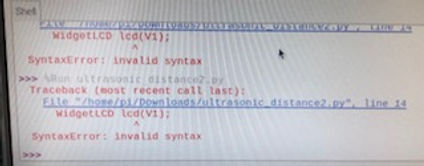
The next error I ran into was the WidgetLCD error shown above. This is another syntax error. I changed the syntax from "WidgetLCD lcd(v1);" to "WidgetLCD(v1);"
I ran into another syntax error with the void setup command. Instead of using "void setup ()", I used "void ()"
I had to remove the semicolon ";" from the "Serial.begin(9600)" line. I don't know the sigificance of the semicolon, but on programs such as MatLab, this prohibits the command from being displayed

Documentation for the pinMode command. I am having trouble getting the proper syntax for this command. To the left shows what this command does and its' parameters. To the right shows the error that I ran into with the syntax.
Note: I may use a different source code because there are so many different syntax errors. It may be designed for a different version of Python, or a different host.
Source: https://www.dexterindustries.com/GrovePi/programming/python-library-documentation/
#define BLYNK_PRINT Serial
#include
#include
#define TRIGGERPIN D1
#define ECHOPIN D2
// You should get Auth Token in the Blynk App. // Go to the Project Settings (nut icon). char auth[] = "Your auth token";
// Your WiFi credentials. // Set password to "" for open networks.
char ssid[] = "your wifi SSID";
char pass[] = "your password";
WidgetLCD lcd(V1);
void setup() {
// Debug console
Serial.begin(9600);
pinMode(TRIGGERPIN, OUTPUT);
pinMode(ECHOPIN, INPUT);
Blynk.begin(auth, ssid, pass);
// You can also specify server: //Blynk.begin(auth, ssid, pass, "blynk-cloud.com", 8442); //Blynk.begin(auth, ssid, pass, IPAddress(192,168,1,100), 8442);
lcd.clear(); //Use it to clear the LCD Widget
lcd.print(0, 0, "Distance in cm"); // use: (position X: 0-15, position Y: 0-1, "Message you want to print") // Please use timed events when LCD printintg in void loop to avoid sending too many commands // It will cause a FLOOD Error, and connection will be dropped }
void loop() {
lcd.clear();
lcd.print(0, 0, "Distance in cm"); // use: (position X: 0-15, position Y: 0-1, "Message you want to print") long duration, distance;
digitalWrite(TRIGGERPIN, LOW);
delayMicroseconds(3);
digitalWrite(TRIGGERPIN, HIGH);
delayMicroseconds(12);
digitalWrite(TRIGGERPIN, LOW);
duration = pulseIn(ECHOPIN, HIGH);
distance = (duration/2) / 29.1;
Serial.print(distance);
Serial.println("Cm");
lcd.print(7, 1, distance);
Blynk.run();
delay(3500);
}
Source code for another iteration of the Ultrasonic Sensor project. I am making several syntax modifications, many of them stated above. This is very similar to the previous source code.
Source: https://www.instructables.com/NodeUltrasonic-Sensor-With-Blynk/

Found the void loop as a syntax error. Instead of leaving "void loop()", I just used "void ()". I also used this mofication with the "void setup()" command.
Current iterations of the modifications to the source code. The video on the left shows the source code derived from the PCBWay tutorial, while the video on the right shows the source code derived from the Instructables document. Both are modified.


Setup of the HC-SR04 Ultrasonic Sensor. The image to the left is a diagram of how the sensor works. The sensor transmits a signal through one of the cylindrical terminals. The signal then reflects off of the surface that is to be measured. Then the other terminal receives the signal. The time between when the signal was transmitted and received can be used to determine the distance from the object, since the speed of sound is relatively constant.
Source for all three images: https://www.pcbway.com/project/sponsor/UltraSonic_Level_Sensor.html
Video demsonstration of the Ultrasonic sensor calibrating the distance from the surface. The sensor will have varying measurements for about a couple of seconds (given the program). Afterward, the measurements a relatively quite consistent, with about a 0.1 cm tolerance. The sensor does not calibrate very quickly. I will speculate that either the sensor is not very high quality or to any machine standards (since it is very cheap), or the program is not set up to calibrate distances quickly. I think that with modifications to the program, this can improve slightly.
The sensor has a relatively loose tolerance of 0.1 cm. I think this is because the sensor is not very high quality, and for our purposes, does not need to be. It will easily complete our tasks at hand.

I imported both RPi.GPIO and time libraries into the Blynk source codes. I imported these exactly like the original Python source code that powered the Ultrasonic Sensor without Blynk.
I did this in order to attempt remove syntax errors. However, this did not remove any. Fortunately, it did not create additional issues with running the program either.
I learned in today's class that the both Blynk tutorial source codes (PCBWay and Instructables) used C programming language, not Python. This is why I ran into so many different syntax errors on both source codes.
the "//" command in C means the comment command, which is the same as the "#" command in Python. The "#" command in C, followed by "include", imports commands or devices. The "char" command in C sets a Character in the program.
Lessons Learned
1. Each motor has different wire connections. Some have two wires, while some have 3. For example, a DC motor has one positive and one negative wire, while a servo motor has a voltage input (+), a control signal and a ground (-).
2. Each motor requires a different wiring setup, requires different GPIO setup on the Raspberry Pi, and requires different power inputs. For example, some motors such as the SG90 servo motor, can run on only the Raspberry Pi voltage, while the DC motors needed the 18650 batteries attached through a motor driver.
3. The vast majority of time spent on this project has been spent troubleshooting errors and challenges along the way. Most likely, the motors and programming are not going to work the first time, even if you attempt to replicate a tutorial
4. Python allows you to extend your capabilities of how you can control electronic devices such as motors. Using a program like LimitOS is very useful because of its ease of use, but there are limited ways that you can use it to manipulate components. For example, you cannot control a motor's angular velocity with LimitOS.
5. A servo motor is essentially a DC motor with an added potentiometer and a gear ratio with a mechanical stop (at least with hobby servos). A servo motor could be converted to a DC motor. This is why the motor kept moving when power, but no software commands, were distributed to the motor.
Sources:
1. https://gpiozero.readthedocs.io/en/stable/recipes.html#
2. https://forum.arduino.cc/t/difference-l293d-and-sn754410ne/278779
3. https://help.realvnc.com/hc/en-us/articles/360002254738-VNC-Connect-Error-Messages
4. https://www.raspberrypi.org/forums/viewtopic.php?t=169402
5. https://learn.adafruit.com/adafruit-raspberry-pi-lesson-9-controlling-a-dc-motor/hardware
6. https://projects.raspberrypi.org/en/projects/physical-computing/14
8. https://m.youtube.com/watch?v=JnKWn6J8MGE
9. https://www.elegoo.com/products/elegoo-uln2003-5v-stepper-motor-uln2003-driver-board
10. https://www.youtube.com/watch?v=xHDT4CwjUQE
11. https://www.digikey.com/en/maker/blogs/2021/how-to-control-servo-motors-with-a-raspberry-pi
12. https://makersportal.com/blog/raspberry-pi-stepper-motor-control-with-nema-17
14. https://www.youtube.com/watch?v=Dc16mKFA7Fo&t=491s
15. https://www.raspberrypi-spy.co.uk/2012/07/stepper-motor-control-in-python/
16. https://bitbucket.org/MattHawkinsUK/rpispy-misc/raw/master/python/stepper.py
18. https://docs.blynk.io/en/getting-started/activating-devices/blynk-edent-wifi-provisioning
19. https://tutorials-raspberrypi.com/raspberry-pi-servo-motor-control/
20. https://bc-robotics.com/tutorials/getting-started-blynk-raspberry-pi-3/
21. https://peppe8o.com/personal-iot-with-blynk-on-raspberry-pi/
22. https://github.com/blynkkk/lib-python
23. https://installvirtual.com/install-python-3-7-on-raspberry-pi/
24. https://peppe8o.com/personal-iot-with-blynk-on-raspberry-pi/
25. https://pypi.org/project/blynklib/
26. https://www.python.org/downloads/
27. https://projects.raspberrypi.org/en/projects/generic-python-installing-with-pip
28. https://tutorials-raspberrypi.com/raspberry-pi-ultrasonic-sensor-hc-sr04/
29. https://www.pcbway.com/project/sponsor/UltraSonic_Level_Sensor.html
30. https://github.com/blynkkk/lib-python/blob/master/examples/esp32/02_terminal_cli.py
31. https://community.blynk.cc/t/lcd-widget-for-blynk-library-for-python/26433
32. https://www.dexterindustries.com/GrovePi/programming/python-library-documentation/
33. https://www.instructables.com/NodeUltrasonic-Sensor-With-Blynk/
My father was very helpful with installing the Blynk Library. Without his assistance, I do not know if I would have been able to find out the issue with installing the Library on the wrong version of Python.