
Medium Fidelity Prototype
In this assignment, students are challenged to enhance the Low-Fidelity prototype of the robot car by introducing modifications and integrating components that align more closely with the characteristics of a final product. Building upon the skills acquired in the Low-Fidelity prototype, the Medium-Fidelity prototype not only reinforces those skills but also introduces new ones. An illustrative example is the utilization of Limit OS, where we initially learned to control the robot over the internet. In this assignment, we further advance our skills by delving into the creation of Python code that enables Limit OS to perform its functionalities.
6/14/2021
The primary focus in refining and enhancing my robotic vehicle involves a redesign of the housing unit. The original housing, constructed from cardboard, served its purpose but falls short of being ideal. I find the limitation in organizing electronic components within the constraints of the box's width and length dimensions less than optimal. Moreover, the excess open space in the box contributes to the robot's larger-than-necessary size, adversely impacting its speed and agility.
A custom-made housing unit offers the advantage of a more compact and space-efficient organization of electronic components. This design allows for stacking components, resulting in a significantly smaller profile.
My strategy involves creating an initial model of the housing unit using Fusion 360. Subsequently, I plan to have the model printed at the DUKE 3D printing lab. Further iterations of housing units can be printed when modifications are required, providing flexibility for physical alterations to the original design.
Embarking on the journey of learning Python programming opens up possibilities to extend control over our robots beyond the limitations of Limit OS. While Limit OS facilitates internet-based control of Raspberry Pi without the need for intricate programming or complex setup—an excellent feature—it does come with some constraints. Specifically, it only permits control over digital inputs and outputs, lacking the flexibility for variability. For instance, while it enables basic motor movements such as forward and backward, achieving variable speeds necessitates individual programming efforts.


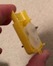
Measurements of the two dimensions of the power source for the Raspberry Pi are provided in millimeters, serving as a reference for the design of the housing unit. Considering that electronic components can be stacked, the housing's profile may not exceed these dimensions significantly.
The initial concept involves stacking the Raspberry Pi and Motor Driver side by side above the power source. Additionally, the plan includes positioning the battery pack underneath the power source.


Measurements of the dimensions of the Battery Pack in millimeters. This allows for me to design an opening in the housing unit that will allow the Battery pack to set into.

The measurement of the diameter of the neck of the motor housing is crucial for my design strategy. I intend to create a semi-cylindrical gap on the motor mounts near each of the four wheels to accommodate the motors. The bottom edge of the motor housing will rest on the edge of the neck of the motor housing, as depicted in the left image. This ensures a stable and secure positioning of the motors within the robotic vehicle.
.jpg)


The measurements of the Raspberry Pi camera module are essential for crafting a housing that provides additional protection, reduces vibration, and minimizes the "swinging" movement observed when the camera module was secured solely by the ribbon connector to the cardboard box. This new design aims to enhance stability and safeguard the camera module effectively.
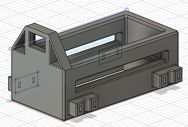
The iteration of the housing unit as of June 14, 2021, represents a significant advancement. While further modifications are anticipated, the current state reflects substantial progress, especially considering the short time frame of one day's work.
6/15/2021

Screenshot of a "Hello World" program on Thorny IDE. This is the first practice program for programming Python.

A screenshot capturing the Python practice loop program is presented, demonstrating the completion of 10 iterations. Due to limitations in the screenshot, not all iterations are visible in the image.

A screenshot showcasing an infinite loop implemented in Python is displayed. The notable distinction between this loop and the previous one lies in its perpetual nature, continuously executing iterations without a predetermined endpoint, unlike the finite number of iterations in the previous loop.

Introducing an additional motor setup for two motors, I am in the process of transforming the vehicle from a "Rear-wheel" drive (with motors located at the back) to a 4-wheel drive configuration. This adjustment serves multiple purposes, including preventing the bottom of the box housing from dragging on the ground, ensuring more consistent control of the vehicle, and potentially enhancing its ability to traverse challenging terrains.
Configuration of the updated control interface for the 4-wheel drive setup involves a notable change. Unlike the previous interface with four options for controlling each direction, the new setup introduces eight options. To achieve synchronized movement of all four wheels, users now need to select four pin controls instead of two.
-
Forward: All four wheels move forward
-
Backward: All four wheels move backward
-
Left: The right motors move forward, and the left motors move backward
-
Right: The left motors move forward, and the right motors move backward
This expanded control interface provides enhanced flexibility and precision in maneuvering the vehicle.
.jpg)

The ultimate configuration of the 4-wheel drive system is now in place.
In terms of speed, the robot maintains a similar pace in both forward and backward directions. Notably, turning left or right is slower in the 4-wheel drive configuration compared to the "rear-wheel" drive setup with the low-fidelity prototype. This is attributed to increased resistance due to motor friction and wheel traction. The robot's weight has significantly increased with the incorporation of the motor driver, battery pack, motors, wheels, and wiring.
Nevertheless, the robot's movements are substantially more stable and consistent than in the previous setup, highlighting the positive impact of the 4-wheel drive configuration on overall performance.
An issue arose with the front wheels where the back wheels operated as usual, but the front two wheels ceased movement. Notably, the front-left wheel exhibited continuous backward movement without any user input. This issue manifested at the initiation of turning on the components.
The video above illustrates this occurrence, wherein the front wheels remained stationary, resulting in slow and resistive turning. Troubleshooting and resolution efforts will be undertaken to address this unexpected behavior.
Addressing the issue of the front wheels not moving involved a series of troubleshooting steps, and the exact resolution is not pinpointed:
-
Tested the battery pack with an LED test (referencing the Low Fidelity Prototype) to ensure its functionality.
-
Added additional wire to the leads on the battery pack, using a female-to-female wire and a jumper wire, addressing potential issues with short and unraveled wires.
-
Replaced the motor driver. The initial motor driver indicated low or no power when the battery pack was turned on. The replacement was implemented as a precaution, even though the original motor driver might have been functional.
-
Removed the ground wire connection for the front motor driver during troubleshooting. The motor controller was tested without the ground wire, and the motors worked correctly. The ground wire connection for the front motor driver may be reevaluated and added later.
Despite these efforts, the 4-wheel drive system is not flawless. When moving backward, the robot exhibits a left turn, relative to an observer looking at the robot from behind. This may require adjustments in PWM values using Python code. The motors' inherent differences, varying friction levels, and tolerance discrepancies in the motor mounts contribute to the system's lack of perfect consistency. Ongoing modifications and refinements may be needed to enhance performance further.


I replaced the robot's wheels, as demonstrated in the video above. The initial set of wheels, on the left, accompanied the motors without pre-soldered leads. The new wheels, on the right, were originally paired with motors featuring pre-soldered leads. The new wheels provide a significantly more snug fit on the mounting pegs compared to the first set. Additionally, they boast a greater width. Unlike the first set, the new wheels have flatter tires, lacking the convex rise in the middle of the width observed in the initial wheels. I believe the new wheels perform slightly better on flat, hard terrain such as floors and shallow carpet, while the first wheels exhibit marginal advantages on softer and less even terrain.

I disassembled the housing unit on a motor (not pre-soldered) to reveal the gearbox on the left. The output end of the motor showed a significant gearing down. In an attempt to enhance the angular velocity of the motor, I modified its gear ratio.
The final setup, depicted below, involved removing the gears between the beveled gear and the driven gear. To address the excessive play for the driven gear, I inserted a part of a straw as a spacer beneath the driven gear and above the motor's pin. This modification eliminates one side of the motor available for mounting a wheel, and the axle protrudes directly from the motor. However, the motor now achieves considerably higher speeds.

Video of how the modified motor runs.
6/29/2021
Continuing with the Medium Fidelity Prototype assignment. The class is going to implement mechanical design into refining our robot cars, as well as incorporating more complex Python programming.

In an effort to enhance space efficiency, I am reorganizing the components of the robot car. The objective is to stack and rearrange these elements to reduce the overall profile of the car while ensuring it retains the necessary components for optimal performance. This restructuring is also aimed at achieving a more balanced distribution of weight across the car, potentially enhancing its speed.
An illustrative example involves stacking both battery packs on top of the portable phone charger, resulting in a smaller profile and a more concentrated weight distribution. The plan is to position the portable phone charger near the bottom of the frame, considering its heavier weight. Above the phone charger, the battery packs will be placed, being lighter but still relatively heavy. The electronic components will be stacked on top since they are the lightest, offering protection against damage.
Temporary securing of the components with scotch tape allows for observation and reference without excessive fixation. This approach strikes a balance, providing enough stability for assessment while remaining easily separable for future rearrangements.
I am in the process of re configuring the Limit OS program for the robot car to enable online control. However, a persistent issue arises where certain motors intermittently run while others cut out. These are not consistent occurrences across the same set of motors, as some run perfectly normally and then cut out, while others may not run at all. This inconsistency manifests randomly across all four motors during the vehicle's operation.
I am presently integrating Python programming into the robot system. Initially, I configured the Limit OS program to assess its functionality under human control.
Moving forward, I will employ the Thonny IDE for Python programming, implementing a simple program to explore the potential of incorporating an autonomous component into the robot. It's important to note that this program won't operate as an Internet of Things application, meaning it cannot be manipulated remotely through an external online source. Instead, the program will be executed solely through the user interface of the Raspberry Pi.

To finalize the project, I am implementing the Button Controlled Robot project from the GPIO Basic Recipes list. The source code is provided on the left, and the schematic is outlined below. While retaining the essence of the code, I will make modifications to the GPIO pins in order to align with the controls established by Limit OS. This approach ensures that the Python programming can be seamlessly integrated, drawing inspiration from the simplicity of the GPIO Basic Recipes project for a smoother replication process.
Source: https://gpiozero.readthedocs.io/en/stable/recipes.html#


I encountered three traceback errors while running the program. The first error occurred with the last command, specifically curses.wrapper(main). Additionally, there was a traceback error related to stdscr = initscr(), even though stdscr = initscr() was not part of the input commands for the program. The final traceback error was associated with fd=_sys.stdout.fileno(), indicating that the terminal could not be found.
Remarkably, directly copying and pasting the source code into the Thonny IDE did not resolve any of these traceback errors. The issues persist despite this attempt.

In the latest version of the Python programming code, I excluded the curses.wrapper(main) command from the command line. This adjustment successfully eliminated all the traceback errors. However, pressing the arrow keys did not initiate movement in the vehicle.
There are a couple of potential issues hindering the motors from functioning with these commands. Firstly, the program is designed to control two motors and one motor controller, whereas the robot car is equipped with four motors and two motor controllers. Secondly, the Keyboard Controlled Robot project is configured to operate with an sn754410 motor controller, while the robot car utilizes L298N motor controllers. These disparities may be contributing to the observed lack of movement.

I opted for a simplified programming approach by initially focusing on powering one motor, specifically the left-rear motor. I utilized the source code from my adapted Motor Python project (refer to the Introduction to Python). For this setup, GPIO pins 20 and 26 were designated for forward and backward operations, respectively.

I am advancing the Python programming by incorporating the back-right motor into the program. GPIO pins 21 and 19 have been assigned for forward and backward operations, respectively. Remarkably, the motors respond in accordance with the program, indicating the continued functionality of the code for autonomous motor control.
I've extended the programming to include both front motors in the control scheme. The program remains functional, and the motors respond autonomously. The front-left motor, referred to as motor3, utilizes GPIO pins 4 and 17 for forward and backward operations, respectively. Similarly, the front-right motor, named motor4, is controlled by GPIO pins 27 and 22 for forward and backward movements.
A notable challenge arises due to the tethered setup with a physical connection between the Raspberry Pi and the monitor. Unfortunately, the VNC viewer is non-functional, limiting the car's range of motion as it is physically linked to the monitor. Despite this constraint, the robot car exhibits rapid movement and agile turns, surpassing the maneuverability achieved by clicking buttons within the LimitOS software. However, the drawback is the loss of the ability to control the vehicle remotely by sharing a link with another device.

Current progress of the 3D printed Housing Unit as of the end of the day on 7/12/2021.

7/13/2021
In an effort to troubleshoot the VNC Viewer, I am making another attempt to establish a headless setup by programming the Raspberry Pi using my laptop computer. This configuration aims to enable programming without a physical wired connection to the robot car, granting it the freedom to move without constraints. While this approach works seamlessly with LimitOS, challenges persist when utilizing programming applications on Raspberry Pi OS.
The encountered issue manifests when attempting to connect VNC Viewer on my computer to the Raspberry Pi. After entering the IP address, the VNC Viewer engages in an extended connection attempt, ultimately resulting in a "Timed out waiting for a response from the computer" message.

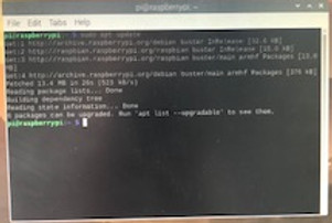
I initiated the troubleshooting process by checking for updates on the Raspberry Pi OS. Employing the "sudo apt update" command in the Terminal Window revealed the existence of six different packages that were eligible for upgrade.

I proceeded to review the list of upgrades and executed the upgrade process through the Terminal Window. The top image illustrates the "apt list --upgradable" command, presenting the list of upgrades available for implementation into the system. In the bottom image, the "sudo apt full-upgrade" command is shown, which actively executes the upgrade process, facilitating the update of the packages.

In an effort to address the VNC Viewer issue, I attempted to reinstall both the VNC viewer and server on the Raspberry Pi. Initially, I ran the "sudo apt update" command, followed by "sudo apt install realvnc-vnc-server realvnc-vnc-viewer." Subsequently, I utilized "sudo raspi-config" to manually install the VNC server, exploring whether this re installation process would resolve the connectivity issue.
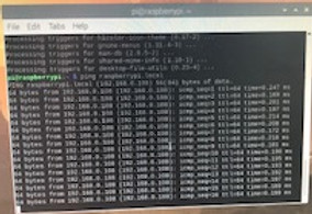
I successfully resolved the VNC Viewer issue by cross-referencing the Raspberry Pi's IP address using the "ifconfig" command in the Terminal Window. Specifically, I inspected the "wlan0" specifications and identified a slight variation in the IP address, with the very last digit being different from the initially entered address. With this correction, I could successfully access VNC on my laptop.
I have successfully recorded a video showcasing the robot's autonomous movement. The same program utilized in the previous iteration powers the robot, with the key difference being the use of VNC Viewer. This enables the robot to move freely without a physical connection to a monitor.
It's worth noting that the robot exhibits quicker and more agile movements compared to those achieved with LimitOS. The enhanced speed and direction changes are attributed to the robot responding more rapidly to software inputs compared to the slower manual input from a human user clicking buttons for different directions.
I successfully programmed the robot to navigate an approximate square autonomously. This is an effective way to test the robot's autonomous capabilities due to its simplicity in both programming and movement.
Initially, I set the turn time to 0.3 seconds, which proved to be too short, resulting in insufficient rotation. Subsequently, I adjusted the turn time to 0.6 seconds, but this was slightly too long. Finally, I settled on a turn time of 0.5 seconds, which is close to a perfect 90-degree rotation.
Additionally, I reduced the straight-line travel time to 1 second instead of two seconds, as limited space did not allow for continuous travel over a longer duration.
Note: The robot moves backward despite the intention to move forward. This discrepancy is attributed to an error in the motor polarity, which is correct for LimitOS but incorrect for Python programming. While it's feasible to command the motors to move backward in the software, I personally prefer aligning the robot's movement with its intended direction.
Code for the original autonomous and square iterations. I am attempting to use a .txt file to implement the code into this website, instead of taking a picture.
I copied the code from Thonny IDE and pasted into the text editor on the Raspberry Pi OS. After this, I coped the code from the text editor on the Raspberry Pi OS and pasted into the notepad application on my Laptop.
I tried copying and pasting directly from the Thonny IDE onto the notepad application, but it did not transfer properly.
Note: The program may work differently with different robots, depending on the speed and type of motors, as well as the layout of all of the components.
I am in the process of refining the Keyboard Controlled Robot project, aiming to integrate features from both the Keyboard Controlled Robot and Motors projects, as the DC motors are equipped with the L298N motor driver.
During the project execution, I encountered an invalid syntax error, as illustrated to the right. I suspect that the commas following the motor commands may be superfluous and could be contributing to this issue.
The relevant code snippet is displayed to the right.
Traceback (most recent call last):
File "/home/pi/Motors_mod2_robot_square2.py", line 12
motor2.forward(),
^
SyntaxError: invalid syntax
I eliminated the comma from the end of the motor2.forward() command, but the invalid syntax error persists. Since I've reached an impasse and cannot progress further, I'll transition to a different component for the time being.

I am beginning the process of fabricating a protective case for my Raspberry Pi. This will enhance its resilience against impacts. To achieve this, I am following the tutorial listed in the sources.
I initiated the project by importing the SLDPRT file for the Raspberry Pi 3B+ generously provided by Nick Corvera (a special acknowledgment to him for offering this valuable resource). Subsequently, I established the necessary offset to create the case. Initially, I elevated the case by 2.1 mm, aligning it with the origin on the z-axis. Following that, I raised the Raspberry Pi by 3.5 mm to account for the case's thickness, as per the tutorial's specifications.

Commencing the sketch for the primary body of the protective case, I am designing it slightly larger around the Raspberry Pi's width and length dimensions. This adjustment is made to accommodate the required wall thickness for the case.

Proceeding with the extrusion process, I extended the design beyond the Raspberry Pi's height dimension to account for the necessary wall thickness. To streamline this operation, I utilized the keyboard shortcut "E" to initiate the extrusion, enhancing efficiency compared to clicking the extrude icon.

Incorporating fillets into the extrusion, I employed the keyboard shortcut "R" to initiate the rounding process, enhancing speed compared to using the icon. I utilized the select edge priority technique, as outlined in the Lessons Learned section, to facilitate the addition of fillets to edges without the risk of affecting faces.

Changing the Opacity Control on the body. This allows the body to be transparent enough to see through it and observe internal components, but also opaque enough so that it is still easy to see the profile of the body.

Creating a projection view and offset to create the pins that secure the Raspberry Pi in place and protrude into the holes on the Raspberry Pi. I was not able to successfully extrude the offset holes.


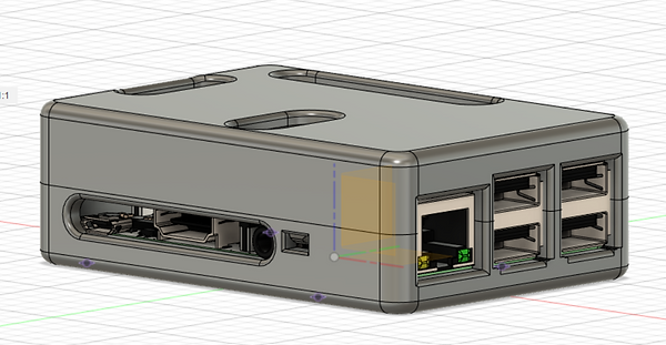
Creating an offset plane to use section analysis for the USB and Ethernet ports


Creating the sketch and extrusion for the USB and Ethernet ports


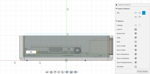
Creating a slot for the HDMI, microUSB and audio ports.


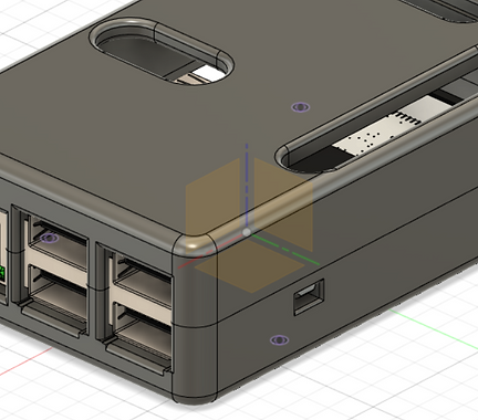
Creating the opening for inserting and removing the SD card.


Creating rounds for the SD Card holder in order to mitigate contacting your fingers against sharp edges when inserting or removing the SD card.

Creating a split body to divide the housing case into top and bottom halves.


Bottom half of the case with a reference model of the Raspberry Pi 3B+

Creating the opening hole for the catch mechanism.


Creating an offset plane to create the protrusions for the catch mechanism.


Extruding and modifying the protrusion for the catch mechanism. This includes chamfers, rounds and a mirror feature.


Adding an offset to create an extrusion for a guide rail on the bottom ofthe case. This includes a cut operation to create the negative effect of the extrusion in the top half of the case


7/14/2021

Extruding the pins for the Raspberry Pi to seat on. I created an extra sketch and extrusion, with the sketch being an overlap of the inner circles and the extrusion protruding from those inner circles.

Incorporating a 1.5-degree draft into the pins ensures a tapered design. This configuration reduces the size at the top, facilitating smoother engagement with the Raspberry Pi's holes. Conversely, the larger bottom enhances a snug friction fit, enhancing overall security.

Adjusting the diameter of the extruded circles for the pins, I decreased it from approximately 2.126-2.167 to 2.12. This modification accounts for the draft angle, preventing the bottom diameter from becoming excessively large. The aim is to facilitate the initial seating of the Raspberry Pi onto the pins within the case.


Received the 3D printed part. The two images above display a side-by-side comparison of the 3D printed housing and the robot car positioned in the cardboard box. The 3D printed housing unit is significantly smaller than the cardboard box.

Assessing the print quality, my impression is that, given the relatively high-quality Makerbot 3D printers and the use of premium ASA filament instead of standard PLA, the print results are less than optimal. It's unclear whether the print settings were suboptimal, if there were issues with the 3D printer, or if common problems with ASA filament contributed to the defects.
During class, there were problems with the Makerbot printers, including difficulties with structural material filling in areas that required support material. Whether these issues influenced the observed defects remains uncertain.
Note: The uneven and stringy material under the motor housing and ledge for the motor drivers serves as support material and is not included in my assessment.


Checking the fitment of the battery pack, I observed that the fit is too tight along the length dimension but nearly perfect along the width dimension. The extrusion depth is slightly excessive for the battery pack, but this is not expected to pose significant issues.
However, challenges were encountered when trying to fit the wires and on/off switch through the back and access them. The opening in the back does not extend high enough to reach the on/off switch. Additionally, I plan to widen the opening to the left along the width dimension to provide more clearance for the wires.
For the next iteration of the housing unit, I intend to increase the length dimension by approximately 1-3 mm and decrease the height dimension by about 0.1 mm.


Checking the fitment of the portable phone charger housing, the length dimension is perfect, but the width dimension is somewhat loose. The extrusion depth (height dimension) is too small, and there is an angle where the front of the phone charger protrudes higher than the back.
For the next iteration, I plan to reduce the width dimension by approximately 0.3-0.4 mm and increase the wall height by about 0.5 mm. I will also address the leveling position to improve the fit.

.jpg)
Setting up the components before transitioning from the low-fidelity prototype housing unit (cardboard box) to the medium-fidelity prototype (3D printed). I am in the process of transferring the components.

Cutting the zip ties that secure the motor to the original housing unit and removing the components from it. The image to the right displays the components spread out and disconnected from the box. My goal is to simplify the wiring setup and eliminate any unnecessary wires.

I acquired some male-to-female wires. I will use them to simplify the male-to-female connections. Originally, I used a female-to-female and a male-to-male wire, or used a female-to-female and jumper wire for any male-to-female connections. Now, I can directly use a male-to-female wire.


The left image shows the original wire setup for one of the motor connections to the L298N motor driver. The right image shows one motor wire (negative) using the original setup, while the other (positive) uses the new male-to-female wire.

The motor wiring setup, with one lead (negative) having both the motor wire and male-to-female wire, while the other (positive) has the motor wire directly connected to the motor driver. I ended up directly wiring the motors to the motor driver because I did not need the additional wire length that the male-to-female wire provided, and it would be simpler to have a direct connection.

The left image displays the motor wiring setup with all four motors directly connected to their respective motor drivers. I will use this setup in the new 3D printed housing unit.
The image below showcases the setup with each component roughly in its respective place. This is how the robot will be wired when the car is fully assembled.


Securing the rear motors to the motor housing unit. The diameter of the cutout for the motor housing is ever so slightly too small, and I did not provide enough clearance for the rubber securing band on top and the overhang that it catches on.
However, I will most likely modify this unit to something completely different for the next iteration because a zip tie connection is not the most secure, and it does not allow you to remove the motors without cutting the zip tie. I will try to make a housing unit that will allow the motors to detach more conveniently.

Showing the final wiring setup of the car and comparing it to the cardboard box beside it. The cardboard box is much larger than the new 3D printed housing unit.

Testing the motor drivers with the battery pack to check their functionality. When I turned on the battery pack, only the motor driver with the battery pack directly connected to it turned on, while the other turned off. Additionally, there was some smoke emanating from one of the motor drivers. The cause of this issue is currently unknown.


Replacing the male-to-male wires that connect power between both L298N motor drivers with two jumper wires. The bare ends of the jumper wires do not deform when bent in the motor driver. Additionally, I replaced the battery pack with another battery pack. With both changes, both motor drivers turn on when the battery pack is turned on.
Testing LimitOS controls on the robot. The LimitOS controls still work perfectly fine. The only issue I ran into was that the battery pack would get disconnected from the male-to-female wire that connected to the motor driver. I needed these extra wires because the battery pack wires could not reach the ports for the motor driver.


Modifying the wire opening for the battery pack on the housing unit. Currently, I cannot access the on/off switch for the battery pack when it is seated inside its opening, which is currently the most pertinent (and aggravating) problem. The opening is not large enough in the height dimension to access the on/off switch.
To solve this, I raised the height dimension by 5 mm, which should provide enough clearance for the on/off switch. I also increased the opening in the width direction by 2 mm on each side of the opening (4 mm total). This is because I want to add slightly more clearance for the wires to pass through. They still pass through perfectly fine, but increasing the clearance should give them more freedom of movement, which will make wiring slightly easier.
I also added a small bridge in the middle of the opening. There are no wires or switches in this area, and I wanted to keep the opening a little more enclosed. I used a center line along the width dimension inside the sketch and added a parameter dimension by setting the width to the left of the center line equal to the right. This should keep the bridge symmetrical across the width dimension, and hopefully prevent it from moving to a location that may interfere with wires or the on/off switch if I make modifications to it.

Modifying the rounds for the wire opening. Since the bridge created two additional edges, I added rounds for both edges.

Changing the clearance for housing the battery pack. I increased the length dimension by 1.3 mm, as it was too long. I also increased the width by 0.2 mm because the battery pack has a tight fit when seating in the housing.
I might make further adjustments to the clearance later, potentially by increasing the length dimension even further while reducing the additional clearance in the width dimension.

Modifying the opening for the portable phone charger. The next most pertinent problem was that when I plug in the USB end of the cable that the portable phone charger uses, the USB cannot connect to the charger since material blocks access to the USB port. You have to lift the phone charger enough so that the USB can connect to the charger, and then the phone charger is sticking out of its housing opening.

Importing STEP Files into Fusion 360, as discussed in today's class. The image shows the DC motor from the parts models list supplied by Nick Corvera.
These STEP Files are very useful. Not only do they allow the reference items to display different colors, similar to their real-life counterparts, but they also enable you to import a specific part of a component that you want to reference. For example, you could import the whole DC motor system or just the motor itself, excluding the housing, gear ratio, or axles.

7/15/2021
I am working on consolidating all motor controls onto a single motor driver. This will result in a more compact and lighter overall system, allowing for the design of a more streamlined housing unit. In the accompanying video, I conducted a test run with the front-right motor, connecting its negative wire to the negative terminal of the rear wheel motor driver.

I've implemented a new wiring setup for the single motor driver conversion. In this setup, I've used a short female-to-female wire and a short jumper wire. The choice of jumper wires over directly plugging wires into the motor driver is to prevent interference caused by the plastic housing on the male ends, as they can sometimes obstruct each other. Additionally, using jumper wires makes the connection less rigid, reducing the risk of damage.
This setup provides flexibility for further modifications without making irreversible changes to the DC motors by stripping their ends.

I've implemented a setup using a single motor driver for the robot car. In the left image, you can see the components arranged on the car. The video on the right demonstrates the car in motion with LimitOS controls.
The GPIO pins connected to the input of the front wheel motor driver are now redundant. Despite this, the LimitOS controls still operate these GPIO pins, and this redundancy does not negatively impact the movement of the robot car.


I am designing a mount for the L298N motor driver to enhance its stability and convenience. The mount will feature a bridge-like overhang, allowing the motor driver to sit securely above the other components. This design ensures a more stable placement compared to simply taping the motor driver on top of the portable phone charger. Additionally, it facilitates easier removal of the charger when necessary.


I am importing the STEP File for the motor driver to use it as a reference for designing posts. These posts will be created to fit securely inside the holes on the motor driver, providing a more stable and secure attachment method than taping the motor driver onto the portable phone charger.
Source: https://drive.google.com/drive/folders/1j3aRdZzISUSH5uV6mCoRdNG1AbujW3u1

I changed the position of the motor driver mount by relocating it to the back of the housing unit. This adjustment allows for easier connection of the battery pack wires directly into the motor driver. To achieve this, I added a male-to-female wire to the battery pack wires to extend their reach to the front of the motor housing where the motor driver is now seated. The image on the right displays the motor driver securely seated on the mount.


In the new arrangement, I swapped the positions of the motor driver and Raspberry Pi. Now, the Raspberry Pi is situated in front of the motor driver, providing easier access to the battery pack and minimizing the need for additional wiring. Additionally, I adjusted the mounting orientation of the Raspberry Pi to be horizontal in relation to the length of the motor driver, enhancing space efficiency and facilitating a closer alignment between the Raspberry Pi and motor driver for simplified wiring.


I created the pins for the Motor Driver mount using a projection sketch, referencing the holes on the motor mount. Utilizing the offset command with a -0.3 mm offset, I ensured a slight clearance for the pins to fit through the holes. Following this, I performed an extrusion to finalize the creation of the pins.
Additionally, I rotated the motor driver reference file to position the inputs for the positive and negative wires from the battery pack towards the back of the housing unit. This adjustment aims to facilitate a more straightforward insertion of the wires directly from the battery pack.


I extended the extrusion on the Motor Driver mount to provide ample space for accommodating the Raspberry Pi. Following this, I inserted the Raspberry Pi STEP File. Using a projection, I referenced the holes on the Raspberry Pi to create pins for it to seat on. Applying a -0.3 mm offset to allow for clearance, I proceeded to perform a 5 mm extrusion to finalize the creation of the pins.

I modified the sketch for the extrusion of the motor driver mount. I reduced the width of the wall thickness on the left side of the mount along the width dimension to better match the components' width. Additionally, I raised the bridge in the height dimension to create more clearance for the portable phone charger to slide in and out smoothly. This adjustment aims to enhance the overall streamlining of the vehicle.

I modified the extrusion under the motor driver mount to eliminate unnecessary protrusion along the width dimension, ensuring a more streamlined design.

Importing the gearbox housing for the DC motor, I aim to integrate half of the gearbox housing with the main housing body as a single unit. This will allow me to insert the motor and gear assembly into the housing and secure the top half using existing screws and the other cover half. This approach ensures a more secure and neat assembly, albeit sacrificing some flexibility in the motors when interacting with uneven terrain.


Attempting to cut away half of the gearbox housing on the DC motor, in hopes of replicating half of the butterfly shell that will be made into one component on the housing unit. This does not work. When I used a cut extrude feature, the other half of the gearbox housing would still be present and was not removed. Only features that I created were removed.


Creating a sketch for the new gearbox housing, I initiated the process by sketching the profile of the housing. To ensure precision and avoid creating the extrusion in open air, I established a midplane for the gearbox housing. Additionally, I employed a projection to trace the screw holes, allowing them to remain accessible for the screws from the motor housing. This approach aims to form a cohesive and secure assembly.


Creating a projection for the axle hole involved making a projection of the curved sides on the edge of the axle. By extending these sides, a complete circle was formed. Additionally, I created a projection of the inner axle, accommodating the metal axle to pass through. To enhance stability, I added a projection for the guide that supports the metal rod where the gears seat. These details contribute to the precision and functionality of the gearbox housing design.

Progress on the sketch for the extrusion of the motor gearbox housing.
Note: I will remove the original motor housing. I am currently leaving it on for reference.


Starting the extrusion for the motor housing, I encountered a challenge in replicating the intricate details of the inside of the gearbox housing. Recognizing the difficulty of achieving a perfect match, I'm considering alternative methods for securing the motor components in future iterations. This adaptability and openness to exploring different approaches contribute to the iterative design process.

Now, I'm progressing to the design of the protective case for the Raspberry Pi. I've begun by crafting openings for the connectors of both the camera module and DSI display. Employing sketches and an extrude to the next object (in this case, the bottom plane of the top half), I'm establishing functional openings. I'm considering potential modifications, such as incorporating slots for enhanced versatility, as I continue refining the design.


Continuing with the protective case design for the Raspberry Pi, I've introduced rounded features to the exterior of the openings at the top of the case. This adjustment aims to enhance user experience, providing a smoother interaction and minimizing potential discomfort associated with sharp edges.
In the latest design iteration for the protective case of the Raspberry Pi, I've replaced the rectangular openings with slots. This modification allows for improved accessibility, enabling users to better insert their fingers into the case. To enhance user comfort, 1 mm rounded features have been added to the slots. It's important to note that the rectangles are still visible for comparison purposes, and they will be removed in subsequent design refinements.


I've incorporated rounded features to the openings of the protective case. This adjustment aims to enhance user comfort and minimize the risk of sharp edges causing damage to wires or cables.

Increasing the size of the round for the slot of the Micro USB, HDMI and audio ports.
I am initiating the 3D printing process for this version of the protective case. In the process of generating the STL file for the G Code, I unintentionally hid the Raspberry Pi reference model, but the top or bottom half remained visible. To address this, I will import two separate STL files—one for the top half and another for the bottom half—ensuring both components are included in the 3D printing procedure.

Importing two separate STL files for the top and bottom parts of the Raspberry Pi protective case. To achieve this, I generated one STL file while concealing the bottom half and another while concealing the top half. In both STL files, the Raspberry Pi reference model was kept hidden.
Printing both halves of the case in a single STL file was not feasible because the STL format treats the entire file as a singular body, even when multiple components are linked in an assembly. This is also the reason for hiding the Raspberry Pi reference file.

Final image of the slicing setup. I utilized the following settings:
-
Raft
-
Layer height: 0.153
-
Infill: 0.35 (35%)
-
Number of shell perimeters: 3
-
Support Material: Breakaway- Model Material
For the material, I used the "Tough" material provided by Makerbot. To enhance the strength of the protective case, which serves as a structural and protective component, I increased the number of shell perimeters to 3 and raised the infill to 0.35 (35%). These adjustments aim to make the case exceptionally robust, possibly even exceeding typical strength requirements.
Additionally, I opted for a reduced layer height of 0.153. While not essential, this adjustment enhances the surface finish of the part by minimizing the visibility of layer lines.

7/16/2021
I am now focusing on modifying software components again, aiming to control the robot using the Blynk application to further explore Python programming.
At present, I've encountered a challenge in programming. While I successfully programmed the robot for autonomous actions, such as moving in a square, progressing to more complex capabilities within the current setup has proven challenging. My current objective is to modify the human driver control aspect of the software, which involves platforms like Blynk. Motor programming, especially for DC motors, presents a more intricate challenge compared to simpler components like LEDs. However, I am in the process of attempting to control the robot through Blynk, experimenting with joystick commands as one option to control the motors since there are no specific DC Motor modules available on Blynk.
Blynk Schematic of the initial robot setup iteration, featuring a single joystick module. Currently, the joystick program is being explored as a means to control the robot, given the absence of a dedicated motor module in the current version of Blynk. While this approach is under consideration, alternative options for control are also being explored.

Text file containing the source code for the initial iteration of the Blynk project. Currently, this is the sole available source code capable of controlling a motor through the Raspberry Pi while utilizing Blynk.
Note: Due to limitations in the Wix website editor, direct embedding of a .py file was not possible. Consequently, the code must be copied from Thonny IDE and pasted into the text editor and notebook application on the laptop.
Source: https://www.thingiverse.com/groups/raspberry-pi564/forums/general/topic:34307
7/17/2021
Executing the square program was performed to verify the robot's ability to move in a square after implementing various modifications.
Creating a new motor housing unit involves designing a squared-off extrusion for the entire motor, aiming to overcome issues encountered with the previous round housing. The round housing allowed for motor rotation, leading to misaligned wheels and hindering the robot's driving performance.


Adjusting the height of the motor housing by extending it to the bottom, as the current design doesn't properly seat on the motor's neck ledge. This modification is applied to all four motors.


Extending the negative extrusion on the motor housing by using a two-sided extrusion to cut material from both sides of the extrusion sketch. This adjustment is made for all four motors.
Setting up Blynk for robot control has encountered obstacles, including issues with the VNC Viewer. In response, a monitor setup is being explored. To troubleshoot and ensure the proper functioning of Blynk and Thonny IDE, an attempt is being made to replicate the initial Blynk LED Project from the "Introduction to Python" section.

The breadboard setup for the Blynk LED project includes a male-to-female wire connecting the positive end of the circuit to GPIO Pin 25. Following this is a 220-ohm resistor, an LED, and a male-to-female wire connecting the negative end of the circuit to the ground on the Raspberry Pi.
The initial problem I encountered was that although Blynk recognized my Raspberry Pi and the program ran correctly at first, the LED failed to illuminate. Additionally, I encountered multiple programming errors after some time, as depicted below:
I acquired the knowledge of capturing screenshots on the Raspberry Pi OS, as documented in the Lessons Learned. Please note that the screenshots may take a while to load due to the Raspberry Pi's comparatively slower computing speed in comparison to a laptop.
Source: https://magpi.raspberrypi.org/articles/take-screenshots-raspberry-pi


In another iteration of replicating the LED project, I connected a 5V power supply to the positive end of the circuit, incorporating a 220 ohm resistor in the setup. I then linked GPIO pin 25 to the end of the resistor and the starting point of the LED. Finally, I connected the negative end of the circuit to the ground on the Raspberry Pi.
The outcome of this configuration led to the LED permanently lighting up, as illustrated in the image to the left.

In another setup for the LED project, I modified the positive end of the circuit to be connected to GPIO pin 17. Additionally, I altered the connection of the end of the resistor and the beginning of the LED lead to be linked with GPIO pin 4. This configuration closely resembles the original LED project.
7/18/2021

In an attempt to replicate the initial LED project, I created a new circuit setup, as shown in the image to the left. However, this configuration proved to be ineffective and did not work.
I changed the input on the LED from v0 to v1. This did not solve any issues.


Upon closer inspection of my breadboard setup, I realized that the initial circuit was placed on the wrong side of the breadboard. The left side shows the previous setup, while the image on the right displays the corrected arrangement.
In the last setup, the breadboard started on the "j" side, where positive leads were on the inside and negative leads were on the outside of the outer edge. The new iteration starts on side "a," with negative leads on the inside and positive leads on the outside to ensure proper polarity.
Despite these adjustments, the issue persisted, and the circuit did not function as expected.

During troubleshooting with my dad, we identified a correlation between the Blynk application's "online" and "offline" indicators and the behavior of the Python IDE running the program. When the Python IDE stops and runs the program, the Blynk application reports the project as offline and online, respectively.
While I'm not certain about the exact meaning of the "online" and "offline" indicators in the Blynk application, it appears that when the Raspberry Pi is marked as offline, the project does not work. Conversely, when the Raspberry Pi is online (according to Blynk), the project may or may not work.

In the latest iteration of the program, I added a "print("Hello World")" command after the "def write_virtual_pin_handler(pin, value):" command to check if the Blynk program would print "Hello world" in the definition. However, upon reviewing the video from the first Blynk LED project, I noticed that the "print("led is off")" and "print("led is on")" commands were not printed in the shell. Therefore, it seems that relying on print statements may not be an accurate way to troubleshoot the program since it did not print these statements initially, yet the program successfully turned on and off the LED.
I checked the voltage output between GPIO pin 4 and the ground GPIO pin, when the Python program was running and the Blynk project was online. Regardless if the button was on or off, the voltage ran 0V.

I attempted to set the new iteration of the housing unit on the 3D printer to take advantage of overnight printing. Initially, I used the original CAD file, hid all components and bodies. However, upon exporting the CAD as an STL and importing it into G Code, multiple reference files were still present, as shown below.

I created a new file for the housing unit, deleting all components. While this method may be inefficient, it ensures a foolproof way to export an STL file without having additional random reference files.

7/19/2021

Changing the wiring between the battery pack and the motor driver. With the new layout of the components, where the motor driver is placed toward the back, it is no longer necessary to use a male-to-female wire as an extension to reach the positive and negative wires into the terminals on the motor driver.
The image to the left compares a direct connection to the motor driver (positive wire) and the use of a male-to-female wire as an extension (negative).
In class today, I learned about the "@blynk.handle_event('write V#')" command in the Blynk Library in Python. I learned that this comand associates a virtual pin innput on Blynk with an event programmed in Python.
One reason for the error was that in Blynk, I was using V0 as the virtual pin for the LED. In Python, I was writing virtual pin 3. Both the Blynk input and the Python event code have to have the same virtual pin associated with them.
The image below shows me changing the virtual pin on the Blynk LED input to virtual pin 3. I belive that this is progress towards troubleshooting the errors, but I still run into the Attribute Error, stating "'Blynk' object has no attribute 'handle_event'".

I am now moving onto controlling the motors with Blynk. I learned in class that controlling the motors is different than controlling the LED project, since the motors use bidirectional current, while the LED uses only unidirectional current. The motors also use different commands to power them, which may, but not necessarily, cause differences in the way current is delivered to them.
I started by creating a project with a slider, with the settings shown to the left. The output is pin V2, since the source code event associates pin V2 with the motors moving. The slider has values from 0 to 100, since that is the PWM range of the source code for the motors.

The source below shows the source code for controlling the motors through Blynk. Special thank you to Yinfi Li for the source code for the project, as well as an explanation in class.
Source: https://github.com/leeinfy/Yinfei-Li-website/blob/main/Blynk.py

I kept running into Attribute errors with the "@blynk.handle_event" command in the Python Source code, so I commented out the commands again, just to see if there are any other errors in the program, and if that would create another error. This eliminated the Attribute Error, and the program ran without errors.
However, nothing happens when I manipulate the slider in the Blynk application. I believe that eliminating the @blynk.handle_event" command removed the association between the slider and the event of the motors receiving current.

Screenshot of the Attribute error after removing the comments by the "@blynk.handle_error" commands.

I attempted to reinstall the Blynk Library on the Raspberry Pi just to see if there was an error with the installation, or if reinstalling it would solve any of the errors.
I installed on pip and pip3, which would be on both Python 2.7.16 and 3.7.7 versions.

Running the Blynk program after the installation. Appraently, the program is able to run successfully without errors in the shell, even though I went back to the original spelling with the Blynk Library commands, as well as removed the comment for the "@blynk.handle_event" commands. This means that the "@blynk.handle_event" is still active.
However, I am still not able to run any of the motors yet. When I move the slider, no motors move.
Setup of the slider and gauge. The left image is the setup of the slider bar. The middle image is the setup of the gauge. The right image shows the layout on the Blynk Motor Project Main page.


Wiring setup of the new iteration of the LED project.
Videos of the new iteration of the Blynk LED Project. The left video shows the LED being turned on and off through Blynk, while the video on the right shows commands being printed in the cell, corresponding to the LED being turned on and off, as well as "Hello World", every time the button is pressed. The "Hello World" command was printed for test purposes to make sure the program was printing commands properly.
Showing the settings for the button and LED. The big discovery was that I should have set the button to a virtual pin (such as pin 0) and I should NOT have set the LED to any specific output. I mistakenly both assigned the LED with a specific output and assigned the Button with a GPIO pin output.


Testing the LED project with a motor to see if the motor would run. The motor definetly does run. It runs unidirectionally and at a constant speed (since the LED code makes current travel unidirectionally and there is no PWM programming to vary the speed.
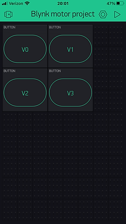
Attempting to complete a similar setup to the LED project, but with 4 buttons corresponding to four motors. This is less than ideal, but a good start to powering the robot through Blynk.
However, I think I will move onto another iteration. The main issue that I am running into is that the LED command only shows one overall GPIO pin, but there are multiple GPIO pins associated with each input on the motor driver.

Wiring layout of the Blynk LED project, without any wires being plugged into GPIO pins. I am using this as reference in order to prepare for another idea for using Blynk on the robot car.

I decided to create headlights for the robot car, since it has relatively few modifications to the LED project, and therefore relatively few things to troubleshoot. This is especially important given that this is one of my first Blynk projects.
I used the wiring setup to the left. I wired both LED in a very similar way as the original LED project. However, I duplicated the wiring and wired a separate circuit for the left and right headlights.
Originally, I tried to wire the left headlight directly to the right headlight while replicating the wirirng circuit of the original LED proejct. I did this by adding wires where the GPIO input ports were plugged in originally, and using male-to-male wires to connect them into the same circuit as the left headlight. This would make Python programming muych easier, since it did not require additional programming for two LEDs. However, I did not end up with this approach because neither LEDs would turn on.
After i attempted to turn on two LEDs electrically, I decided that software was the best approach to controlling each LED individually. I set up a program with two buttons. Initially, I set them both equal to virtual pin 0. This did not work, because both buttons would turn on at the same time when I pressed them. The LEDs would also remain turned off, even though the program ran without errors and the Blynk application stated that the Raspberry Pi was online.

Running the program where each LED is turned on and off. I added a separate @blynk.handle_event series of commands, where I set the other LED to virtual pin 1, and created a new variable for the LED called "led2". I defined this variable with its respective GPIO pin as well as added it in the second @blynk.handle_event.
A text file of the code is below.
Running a program where there is an additional button for both LEDs to be turned on at the same time. I did this by copying and pasting another event, and set both led variables to be equal to 1 and 0 when the button is pressed or not pressed, respectively.
A text file of the code is shown below.
7/20/2021

I installed the camera module on the robot, which is a requirement for the medium fidelity prototype. I can use LimitOS as the driving software in order to use the camera while driving the robot.


Re-securing the breadboard for the headlights with double-sided tape. Originally, I secured it with scotch tape. Scotch tape is a great way to temporarily secure components on the robot, since the tape is easily removable, yet still secure enough to hold small and lightweight components. This is very useful for creating and rearranging the layout of components for the robot car.
However, I wanted a more secure attachment for the headlights, because the robot will be moving around and changing movements quite quickly. I want the breadboard to be extra secure so that the electrical components would be less prone to falling out or sustaining damage to them. The result also looks cleaner, since there is no exposed adhesive or tape.

I am now managing the wiring setup to make everything more secure, streamlined and simple. I shortened the cable for the camera module, as shown on the left image. I also used drinking straws to secure the motor wires together, as shown on the right image. I also replaced some longer

I tested running the robot with both the Blynk application and LimitOS to see what would happen when both programs run simultaneously. I initially started the Blynk program, then started LimitOS. I used the setting for both headlights to turn on when I started Blynk.
Initially, both headlights were turned on. Then I moved the robot forward and they still remained turned on. When I moved the robot backward, the ligths would turn off. With left and right turning, the side with the opposite side of the direction that the robot was turning remained on, while the same direction was turned off.
Essentially, each side that has the motors moving forward leave the headlights turned on, while the motors moving backward turn off the headlights. I do not know why this is because the motors and headlights use differnet GPIO pins.

Attempting to troubleshoot the LimitOS controls. The robot car wheels often moved in directions different than what the driver controls intended for them to travel. Sometimes, one side of the car would not travel at all.
As shown above, I made a couple of modifications to the setup, but it still did not solve the issues.
Attempting to fix the Button mappings on the LimitOS driver controls after making more modifications. I eliminated four of the GPIO pins, since I am only using one motor driver, which makes it unnecessary. I wanted to clean it up to make the setup more simple as well as less prone to errors.


I am testing the motor wires in a different motor driver to see if the issue is with an motor port on the right side of the motor driver. I ended up replacing the motor driver, but I still am not exactly sure if that is the issue. I was able to get several of the controls for the right motors to run with a new motor driver, but the previous motor driver worked relatively shortly before the errors occurred.
I replaced the motor driver anyway.

I ended up taking out the male-to-female wire and jumper wires from the motors in order to reduce the number of sources of error and simplify the setup. Despite that there is some crowding with the male ends of the wires, the wires are still able to slide into the input ports for the motors without forcing them in. The end wires may bend, but they do not seem to incur as much wear as initially thought of.

New pin setup for the motors. I wanted to group the input wires close together on the GPIO pins for organization sake, so I modified the GPIO pins for the left motors, changing them to GPIO 16 and 19.
I re registered the Raspberry Pi as a new device and replicated the above layout. This process solved the issue.
Below is an image of the final iteration of the user controls on the Raspberry Pi.


Final setup of the Medium Fidelity Prototype.
Video of the robot being controlled by Blynk.
Lessons Learned
7/13/2021
7/15/2021
1. In Fusion 360, if you use "select Edge Priority" it will allow you to select edges on an object for adding rounds without selecting faces of the object. This is useful if you only want to round edges and do NOT want to round any faces.
2. Using the opacity control command allows a body to be transparent enough to see through it and observe internal components, but also opaque enough so that it is still easy to see the profile of the body.
3. The projection command allows you to create extrusions and other features around a particular design feature and design face, instead of just a planar surface. In this example, it is creating the pins that stick into the holes of the Raspberry Pi.
4. When converting CAD Files into STL Files, if you hide an object from view and export the CAD model as an STL file, the hidden object does NOT show up in the STL File.
5. In Raspberry Pi OS, you can create screenshots with the "Scrot" command on the Terminal Window. In the Terminal Window, Type "Scrot -d 3" in order for Raspberry Pi OS to take a screenshot of its screen with a three second delay.
(example of a Screenshot):


Sources:
1. https://www.raspberrypi.org/magpi-issues/Beginners_Guide_v1.pdf
2. https://www.autodesk.com/products/fusion-360/overview?term=1-YEAR
3. https://www.imore.com/how-take-screenshot-raspberry-pi
4. https://gpiozero.readthedocs.io/en/stable/recipes.html#
5. https://www.hackster.io/RedMnMGuy/4-wheel-drive-dc-motor-control-for-raspberry-pi-1300c4
6. https://linuxconfig.org/how-to-change-from-default-to-alternative-python-version-on-debian-linux
7. https://gpiozero.readthedocs.io/en/stable/recipes.html#
8. https://www.raspberrypi.org/forums/viewtopic.php?t=169402
8. https://www.raspberrypi.org/documentation/raspbian/updating.md
9. https://www.raspberrypi.org/documentation/remote-access/ip-address.md
10. https://www.raspberrypi.org/documentation/remote-access/vnc/
11. https://www.youtube.com/watch?v=E0NVC8xhf3I
12. https://www.youtube.com/watch?v=AZSiqj0NZgU&t=3s
13. https://drive.google.com/drive/folders/1PuOY-NFN29vs9kIJb4Zdt05YfXoK5ByG
14. https://grabcad.com/library/3-6v-dc-gearbox-electromotor-1
15. https://grabcad.com/library/l298-dc-motor-driver-1
16. https://drive.google.com/drive/folders/1j3aRdZzISUSH5uV6mCoRdNG1AbujW3u1
17. https://www.thingiverse.com/groups/raspberry-pi564/forums/general/topic:34307
19. https://blynk.hackster.io/ashshaks/joystick-controlled-car-b2df84
21.https://www.youtube.com/watch?v=iSG_8g6KyGE
22. https://magpi.raspberrypi.org/articles/take-screenshots-raspberry-pi
23. https://bc-robotics.com/tutorials/getting-started-blynk-raspberry-pi-3/
24. https://github.com/leeinfy/Yinfei-Li-website/blob/main/Blynk.py
25. https://pypi.org/project/blynklib/
26. https://www.youtube.com/watch?v=QEC1rriH9Ek
27. https://www.raspberrypi.org/documentation/configuration/camera.md
https://github.com/blynkkk/lib-python/blob/master/examples/esp32/02_terminal_cli.py
Special Thank you to Nick Corvera for providing a Google Folder of the reference files of the CAD models.
Special Thank you to my dad for helping me continue to troubleshoot Blynk programming.